Technical & Economic Feasibility Study of Proposed Pump Storage Power Plants at Kuda Oya, Mul Oya, Gurugal Oya, and Dambagasthalawa
Energy Systems Electronics受け取った 04 Oct 2024 受け入れられた 05 Nov 2024 オンラインで公開された 06 Nov 2024
ISSN: 2995-8067 | Quick Google Scholar
Next Full Text
The Intersection of Artificial Intelligence in Public Health and Personalized Cancer Therapy


受け取った 04 Oct 2024 受け入れられた 05 Nov 2024 オンラインで公開された 06 Nov 2024
This paper presents a Technical and Economic Feasibility Study of proposed Pumped Storage Power Plants (PSPPs) at KM (Kuda Oya, Mul Oya), KMG (Kuda Oya, Mul Oya, Gurugal Oya), KG (Kuda Oya, Gurugal Oya), and Dambagasthalawa. Sri Lanka aims to transition away from a coal-dominant electricity sector within the next decade, aligning with sustainability goals outlined by the United Nations. In pursuit of affordable and clean energy sustainability, the Sri Lankan government has opted to shift its long-term energy policy towards renewable sources, departing from fossil fuels. Despite this shift, a significant portion of Sri Lanka's electricity consumption—approximately 600 MW from oil and 900 MW from coal—persists. The country now aims to source 80% of its energy from renewable sources, necessitating a focus on underutilized opportunities. In selecting the best candidate sites for Pumped Storage Power Plant (PSPP) design, comprehensive hydrological and sedimentation studies play a pivotal role. In this endeavor, we endeavor to re-rank the selected candidate sites for pumped storage power plants considering technical & financial feasibility by conducting comprehensive hydrological and sedimentation studies. These studies are pivotal for assessing the feasibility and long-term viability of potential sites, aiming to select the most sustainable candidate site in every aspect. Therefore, the primary objective of this research is to conduct a thorough hydrologic study of the proposed KMG and Dambagastalawa pump storage power plants, focusing on identifying potential energy-saving opportunities in pumping when these plants operate as open-loop systems. This study will analyze the hydrology of the upper ponds of the Kuda Oya, Mul Oya, and Gurugal Oya (KMG) pump storage power plants, and the Dambagastalawa Oya pump storage power plant, assessing the potential reduction in pumping energy. Such insights are essential for optimizing the design and operation of PSPPs to ensure economic viability and sustainable energy generation. Furthermore, this research addresses the importance of studying sedimentation in both the upper and lower ponds of the KMG and Dambagastalawa pump storage power plants. Sedimentation calculations will be performed to determine reservoir lifetimes, offering critical insights into the long-term feasibility and maintenance requirements of these projects. The findings of this study are expected to provide valuable guidance to policymakers, investors, and PSPP designers in selecting the most suitable sites for addressing Sri Lanka's peak power demands and urgent electricity needs. By emphasizing the significance of hydrological and sedimentation studies, this research underscores the importance of thorough site assessment in optimizing the design and operation of Pumped Storage Power Plants.
United Nations introduced the Sustainable Development Goals 2030 agenda [1] to make a better and sustainable future for all. In 2015, September Sri Lanka and another 192 countries adopted the 2030 agenda for sustainable development.
To achieve SDG goal 7 which is affordable & clean energy, the Sri Lankan government made a policy with the objective of increasing the renewable energy share percentage of electricity generation up to 80% in 2041 [2]. Ceylon Electricity Board (CEB) would not be able to install a large number of economical fossil fuel power plants. Further, CEB forecast in 2030 maximum demand would be 4872MW [2]. It is almost double the current maximum demand. To fulfill this requirement CEB needs to increase the generation capacity immediately. Furthermore, CEB started to promote domestic roof-top solar systems and wind power generation where large hydropower generation capacity was almost absorbed [3]. Daytime power generation will increase and can create a positive gap between electricity generation and demand in the daytime.
If CEB can store excess and cheap power generated in off-peak and daytime, where generated power is greater than the demand, then it can use night peak and other necessary times where the generation cost is high. It is called as “Peak saving method”. But solar power generation with a battery bank, is costly. CEB identified pump storage power plants are one of the suitable options for storing energy [3].
Pumped Storage Power Plants (PSPP) were found in Italy and Switzerland in the 1890s, and PSPP was first used in the United States in 1930. A PSPP can primarily generate required electric power during the peak hours or day time and when the power demand is lower, water is pumped up from the lower pond to the upper pond using the excess electricity generation capacity of base-load thermal power plants. Consequently, water is circulated to generate electric power. PSPPs may be classified into “closed loop PSPP” type and “Open loop PSPP” type.
In “Closed loop PSPP”, there is no natural inflow into the upper pond or the flow is negligible, and water pumped up to the upper pond is recirculated between the two ponds for power generation. In the “Open loop PSPP” type, the power plant is made with the natural inflow, and the water pumped into the upper pond is used for power generation. This would save energy used for pumping according to the capacity of natural inflow into the upper pond.
In addition to providing lower-cost peak-time power generation, a PSPP can also act as an emergency reserve during sudden outages in the system and also can be helped to withstand vulnerable blackouts. PSPP acts as an ideal fast response reserve assisting economic dispatch. Since PSPP can store electric power, it improves the quality of the electricity supply and the reliability of the sector as a whole through the improved provisions for frequency control and reactive power supply. Accordingly, a PSPP can improve the reliability of a power system. Owing to these advantages of PSPP it allows the power system to be developed with larger penetration of renewable energy sources in a flexible manner.
In a system inclusive of both thermal and nonthermal sources, PSPP acts as a steadfast intermediary in the overall system coordination. Studies have indicated the potential for PSPP in Sri Lanka considering various aspects as in Figure 1, Sri Lanka witnesses a peak demand for electricity during 1800 - 2100 hrs.
It is estimated that 17% of the total energy is consumed during this time period [4]. Owing to this peaking scenario, Sri Lanka needs to find a mechanism to serve the fluctuating demand. This can be achieved by the use of PSPP. Since Norochcholai coal power plants are planned to be fully connected to the grid to cater to the base load, the introduction of PSPP would increase the efficiency of these large-scale coal power plants as well. Furthermore, the maintenance costs of certain types of gas-fired power stations increase sharply burdening the national economy when they are forced to reduce load at night. This is due to the fact that the thermal plants are much less able to respond to the sudden changes in electrical demand, potentially causing frequency and voltage instability. Pumped storage plants, like other hydroelectric plants, can respond to load changes within seconds.
Now, PSPP facilities can be found all around the world. According to the 2021 edition of the Hydropower Market Report, PSPP currently accounts for 95% of all utility-scale energy storage in the United States. America currently has 43 PSPP and has the potential to add enough new PSPP plants to more than double its current PSPP capacity [5]. Those are statistical data in a global context and unfortunately in a local context, Sri Lanka still did not have any PSPP. In 2009, the survey identified suitable locations and water streams to install pump storage plants including Kuda Oya, Mul Oya, Gurugal Oya & Dambagasthala Oya to fulfill the peak power requirement of the country. Moreover, in 2015, a survey was done by the Japan International Cooperation Agency, and the study aimed at propounding optimal power generation for peak power demand in Sri Lanka that will contribute to development and improvement in Sri Lankan economy and living standard in a quick and efficient manner through stable supply of electricity and relief of peak power shortage and Fluctuation in electric supply capacity according to season [6].
The study aims to evaluate the technical and economic feasibility of pumped storage power plants (PSPP) at Kuda Oya, Mul Oya, Gurugal Oya, and Dambagasthalawa. This research analyzes site-specific data such as hydrology, geology, and sedimentation to determine the most feasible locations for PSPP installations. The feasibility study includes both manual calculations and HEC-HMS models [7], along with comprehensive sedimentation analysis. The study is based on catchment area calculations and data derived from 1:10,000 maps. The locations under study are Kuda Oya, Mul Oya, Gurugal Oya, and Dambagasthalawa pump storage power plants (Table 1). The map, as referenced in the study (Figure 2), provides a catchment area of the Gurugal Oya upper pond.
| Table 1: Selected PSPP’s Upper and Lower Ponds. | ||
| Pump Storage Power Plant (PSPP) |
Upper pond | Lower pond |
| KM PSPP | Mul Oya | Kuda Oya |
| KG PSPP | Gurugal Oya | Kuda Oya |
| DM PSPP | Pattipola | Dambagastalawa |
This study was performed as follows,
1. Catchment area calculation (upper ponds)
2. Collecting rainfall data
3. Runoff flow calculation (manually calculated and verified with HEC-HMS software)
4. Calculation of each pond's natural inflow
5. Pumping energy saving due to natural inflow
The data for this feasibility study is sourced from several key repositories and databases:
The catchment area calculation performed in this study used 1:10,000 maps, with the map numbers referenced in Table 2 as '61/15' and '61/14.' These map numbers serve as identifiers for specific map sheets, which are commonly used for detailed topographical studies and hydrological assessments at each site (Table 3).
| Table 2: 1:10000 scale topographical Maps used for Catchment area Calculation. | |
| Pond Name | Related 1:10,000 Map Nos |
| Gurugal Oya upper pond | 61/15, 61/14 |
| Mul Oya upper pond | 61/15, 61/20, 62/11 |
| Pattipola upper pond | 68/15 |
| Table 3: Calculated Catchment areas. | |
| Location | Catchment Area(km2) |
| Gurugal Oya Upper pond | 4.2 |
| Mul Oya Upper pond | 14.86 |
| Pattipola Upper pond | 1.468 |
Rainfall data from the catchment area were collected from the Meteorology Department for this study.
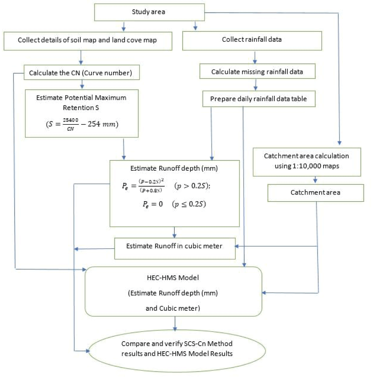
Manual runoff calculations are performed using the Curve Number (CN) method [8]. This method, developed by the USDA Soil Conservation Service, is widely used for estimating direct runoff from a rainfall event based on land use, soil type, and hydrological conditions. The HEC-HMS [7] is a widely used software for simulating rainfall-runoff processes in watersheds [8]. This model is used to verify manual calculations. The flow chart (Figure 3) outlines the sequence of steps followed in the study, beginning with data collection and ending with the comparison of manual and model-generated results.
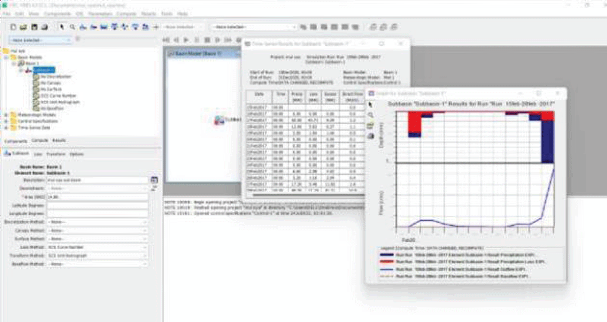
This HEC-HMS model (Figure 4) shows the estimated runoff depth based on the given input data.
Finding the pump discharge rate (KM Pump storage power plant)
Basic design configurations based on Tharanga Wickramarathna’s study [6].
Design Discharge = 80.2 m3/s
Peak duration, Hours = 6 hr
Total discharge of water per day = 6 hr × 60 × 60 × 80.23/s = 1732320 m3
If the power plant pump working hours are 18 hours,
Pump discharge = 1732320 m3/(18 × 3600)
Pump discharge = 26.733 m3/s
Required penstock diameter for discharge
Assume the penstock Making Galvanized iron, Then n = 0.016
D = 2.69 × (n2 × Q2 × L/Hg)0.1875
D = 2.69 × (0.0162 × 80.22 × 2320 / 366.7)0.1875
D = 4.18 m
Finding the discharge velocity
D = (4 × Q/V × p)0.5
V = 4 × Q/D2 × p
V = (4 × 80.2)/(4.182 × 3.1416)
V = 5.844 m/s
Finding the pumping velocity
V = (4 × 26.733)/(4.180.5 × 3.1416)
V = 1.948 m/s
Therefore, maximum discharge velocity = maximum pumping Velocity = 5.844 m/s
Finding the Reynolds number
Re = 2.44 × 10⁷ kgN-1m-5S
Finding pipe relative roughness factor
Pipe Relative Roughness Factor = e/ = 0.06 mm/4.18 × 103 mm steel Welded and Seamless e = 0.06 mm)
Pipe Relative Roughness Factor
= 1.435 × 10⁻⁵
friction factor factor f = 0.009293
(Reference: Moody Graph)
Find the head loss due to Friction
hL = 8.99 m
Find the total effective head
Total effective head for pumping
= 366.7 + 8.99 m
= 375.69 m
Total pumping energy calculation
Pumping power
P = 8.5 × Q × He × 10-3 MW
P = 8.5 × 26.733 × 375.69 × 10-3 MW
P = 85.36 MW
Yearly pumping energy E = 85.36 MW × 24h × 365
E = 747.753 × 10³ MWh
Yearly pumping Water Volume (closed loop)
= 1732320 m3/day × 365 days
= 632.3 × 10⁶m3
= 13575.22 MWh
As above, calculations for pumping energy savings were performed for the KM Pumped Storage Power Plant using inflow volume data from 2016 to 2020, with results presented in Table 4. Similar calculations were conducted for the KG and Dambagasthalawa Pumped Storage Power Plants, with results shown in Tables 5,6.
| Table 4: Mul Oya UP Yearly inflow volumes. | |
| year | Inflow Volume (cubic meter) |
| 2016 | 11479206.07 |
| 2017 | 19106295.46 |
| 2018 | 27836772.45 |
| 2019 | 18116298.56 |
| 2020 | 14054416.54 |
| Table 5: Gurugal Oya UP Yearly inflow volume. | |
| year | Inflow Volume (cubic meter) |
| 2016 | 1875391.25 |
| 2017 | 3966168.224 |
| 2018 | 5333538.57 |
| 2019 | 4119010.557 |
| 2020 | 2682605.383 |
| Table 6: Pattipola UP Yearly inflow volume. | |
| year | Inflow Volume (cubic meter) |
| 2016 | 446818.8818 |
| 2017 | 1337846.147 |
| 2018 | 1518672.438 |
| 2019 | 1464600.085 |
| 2020 | 914216.538 |
Sedimentation yield calculation: The Dandy-Bolton formula is often used to calculate the sedimentation yield. The formula uses catchment area and mean annual runoff as key determinants to give a yield value. It does not differentiate in basin-wide smaller streams and their characteristics. Dandy and Bolton's equation calculates all types of sediment yield, i.e. sheet and rill Erosion, Gully Erosion, channel Bed, bank erosion, mass movement, etc.
Sediment yield by the Dendy-Bolton formula For Q < 2:
S = 1280 Q0.46 [1.43 - 0.26log(A)] (1)
For Q = 2:
S = 1965 e-0.055 [1.43 - 0.26log(A)] (2)
Where;
Q (in) - Runoff
>A (mi2) - Catchment Area
S (tons/mi2/yr) - Sedimentation Yield
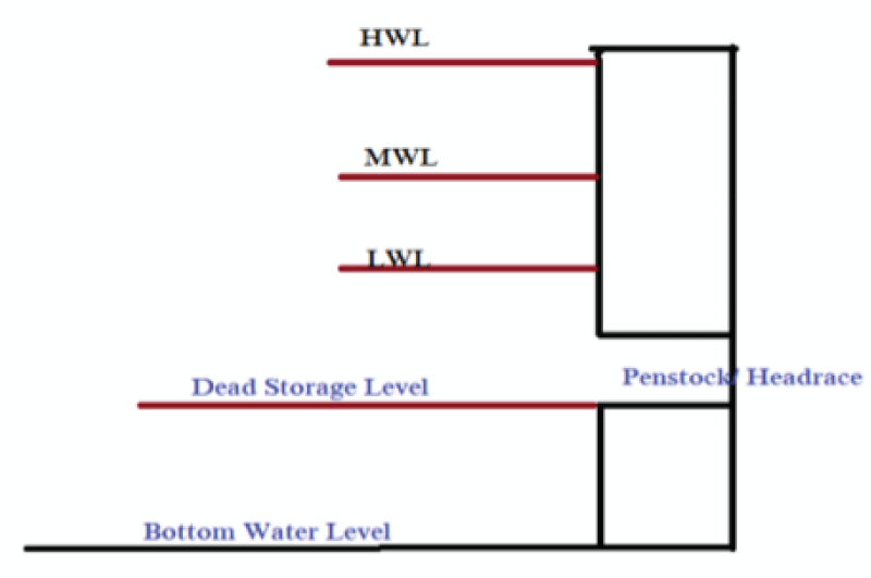
Reservoir lifetime (Figure 5) is calculated manually by using the general formula given below and using Microsoft Excel to find reservoir lifetime.
(3)
Cumulative Sedimentation Volume (m3) = ?Tt=1 Sediment Volume (4)
Dead Storage Volume Balance (m3) = (Initial dead storage volume) – (Cumulative Sedimentation Volume) (5)
Annual Sediment load to reservoir (Kg = Sediment Yield (Kg/Km2 per year) * Catchment Area (Km2) (6)
Using sediment yield data calculated with the Dendy-Bolton formula (Equations 1, 2, 3, 4, 5, and 6), the reservoir lifetime can be calculated.
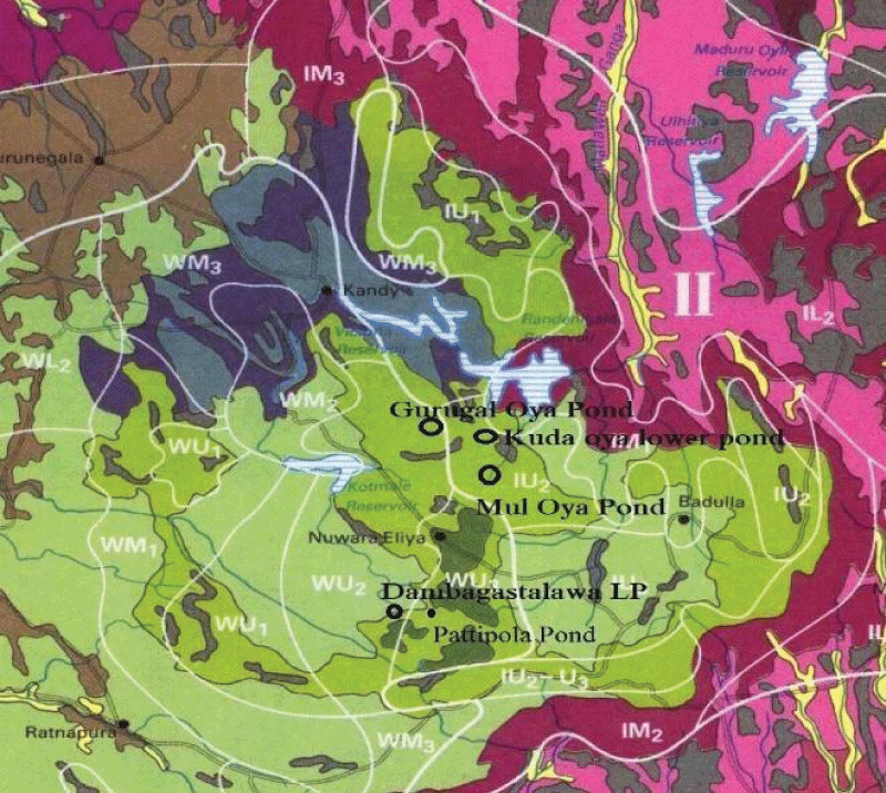
Utilizing the Soil Map of Sri Lanka, the identified soil group is Red Yellow Podzolic. Within this classification, specific soil types have been identified (Figure 6) [9,10].
This section analyzes natural inflow, sedimentation rates, and soil composition for the Mul Oya, Gurugal Oya, and Pattipola reservoirs. The results highlight natural inflow’s role in reducing energy needs, sedimentation’s impact on reservoir lifespan, and soil considerations for construction. Together, these insights support the feasibility and sustainability of the proposed pumped storage systems.
Manual calculations were performed using the collected data and equations [7] to compute the runoff and inflow volume. The HEC-HMS model processes [8] the collected data and provides the results. A comparison of the results from the manual calculations and the HEC-HMS model is conducted for verification. The yearly inflow volume results for Mul Oya, Gurugal Oya, and Pattipola upper ponds are as follows (Tables 4-6).
Using inflow volume data from 2016 to 2020, the calculated energy savings for the Pumped Storage Power Plants due to natural inflow are tabulated below in Tables 7-9.
| Table 7: KM Pump storage power plant Energy Saving due to natural inflow. | ||
| year | Inflow Volume (cubic meter) | Yearly Energy Saving(MWh) |
| 2016 | 11479206.07 | 13575.22 |
| 2017 | 19106295.46 | 22594.95 |
| 2018 | 27836772.45 | 32919.55 |
| 2019 | 18116298.56 | 21424.19 |
| 2020 | 14054416.54 | 16620.64 |
| Table 8: KG Pump storage power plant Energy Saving due to natural inflow. |
||
| year | Inflow Volume (cubic meter) | Yearly Energy Saving(MWh) |
| 2016 | 1875391.25 | 3540.83 |
| 2017 | 3966168.224 | 7488.32 |
| 2018 | 5333538.57 | 10069.98 |
| 2019 | 4119010.557 | 7776.89 |
| 2020 | 2682605.383 | 5064.89 |
| Table 9: Dmbagastalawa PSPP Energy Saving due to natural inflow. | ||
| year | Inflow Volume (cubic meter) | Yearly Energy Saving(MWh) |
| 2016 | 446818.8818 | 641.69 |
| 2017 | 1337846.147 | 1921.33 |
| 2018 | 1518672.438 | 2181.02 |
| 2019 | 1464600.085 | 2103.37 |
| 2020 | 914216.538 | 1312.94 |
The identified soil types are tabulated in Table 10.
| Table 10: Identified Soil Types. | |
| Location | Soil Type |
| Gurugal Oya UP | Red Yellow Podzolic with mountain regosols |
| Mul Oya UP | Red Yellow Podzolic with mountain regosols |
| Kuda Oya LP | Red Yellow Podzolic with mountain regosols |
Using sediment yield data calculated with the Dendy-Bolton formula (Equations 1, 2, 3, 4, 5, and 6), the results are tabulated in Table 11.
| Table 11: Reservoir Life time calculation and Results. | |
| Reservoir | Result |
| Muloya upper Reservoir | Dead Storage Volume Zero between year 530 & 531.Therefore, reservoir life time is 531 Years. |
| Gurugal Oya Reservoir | Dead Storage Volume Zero between year 243 & 244. Therefore, reservoir life time is 244 Years. |
| Kuda Oya Lower Pond | Dead Storage Volume Zero between year 208 & 209. Therefore, reservoir life time is 208 Years. |
| Pattipola Reservoir | Dead Storage Volume Zero between year 368 & 369.Therefore, reservoir life time is 369 Years |
| Dambagasthalawa Lower Pond | Storage volume Zero between year 191 & 192. Therefore, reservoir life time is 192 Years. |
Based on the calculations, it is evident that the annual energy savings attributed to the natural flow of upper ponds are substantial, averaging approximately 22,000 MWh for the KM PSPP, 7,000 MWh for the KG PSPP, and 1600 MWh for the DM PSPP. Leveraging this natural flow can significantly reduce pumping time, thereby enhancing plant efficiency. This presents an additional advantage for the plants in terms of operational cost reduction and overall sustainability.
Furthermore, the mathematical analysis indicates that the lifetimes of all reservoirs exceed expectations, ensuring long-term viability and stability for the PSPP. This underscores the robustness of the selected sites and reinforces their suitability for addressing Sri Lanka's energy demands in a sustainable manner.
One limitation of the study is the reliance on historical data for rainfall and inflow estimations. Climate change may alter precipitation patterns, which could affect future inflow rates and reservoir sedimentation. Additionally, the study does not fully explore alternative inflow enhancement methods, such as water diversion or artificial reservoirs, which could improve the system's reliability during dry periods.
This study highlights the viability of Pump storage power plants as a reliable solution for meeting Sri Lanka’s peak energy demands, emphasizing the role of natural inflows in reducing energy costs and optimizing system performance. With effective sedimentation management and soil stabilization techniques, these sites provide long-term, sustainable energy storage that aligns with Sri Lanka’s renewable energy goals. Moving forward, careful consideration of evolving hydrological patterns and environmental impacts will be essential to maintain the effectiveness of these systems.
The global challenge for government transparency: The Sustainable Development Goals (SDG) 2030 agenda. 2015.
Annual reports. 2021. Available from: https://www.pucsl.gov.lk/annual_reports/annual-report-2021/
Long-term generation expansion plan 2020-2039. 2020.
Vivekananthan RC, M.A.S.A.M.A.R.M.F.A., Incorporating pumped storage power plant in the Sri Lankan electricity sector. 2011.
S. Hydropower Market Report. 2021.
T.A.P W. Study on pumped storage power plants and optimization for peaking power generation in Sri Lanka. Volume II, Part II: 34-70. 2013.
S. Department of Agriculture. Estimating runoff volume, National Engineering Handbook. July 2004. Available from: https://directives.nrcs.usda.gov/sites/default/files2/1712930818/31754.pdf
HEC-HMS Technical Reference Manual.
Dharmasena P. Climate and soil. 2022. Accessed 06 Dec 2021. Available from: https://www.researchgate.net/publication/357047948_Training_Workshop_on_Participatory_Land_Use_Planning_held_on_6_th_-7_th_December_2021_at_SLFI_Colombo_PART_2_-CLIMATE_AND_SOIL
Moormakn FR. New approach to identification and classification of the most important soil groups in Ceylon. 1961. Available from: https://edepot.wur.nl/482354
Pirathapan T, Ponnamperuma R, Polgasdeniya P, Wickramarathna T. Technical & Economic Feasibility Study of Proposed Pump Storage Power Plants at Kuda Oya, Mul Oya, Gurugal Oya, and Dambagasthalawa. IgMin Res. November 06, 2024; 2(11): 915-921. IgMin ID: igmin267; DOI:10.61927/igmin267; Available at: igmin.link/p267
次のリンクを共有した人は、このコンテンツを読むことができます:
1Electrical Superintendents, Ceylon Electricity Board, Sri Lanka
2Electrical Engineer, Ceylon Electricity Board, Sri Lanka
Address Correspondence:
T Pirathapan, Electrical Superintendents, Ceylon Electricity Board, Sri Lanka, Email: [email protected]
How to cite this article:
Pirathapan T, Ponnamperuma R, Polgasdeniya P, Wickramarathna T. Technical & Economic Feasibility Study of Proposed Pump Storage Power Plants at Kuda Oya, Mul Oya, Gurugal Oya, and Dambagasthalawa. IgMin Res. November 06, 2024; 2(11): 915-921. IgMin ID: igmin267; DOI:10.61927/igmin267; Available at: igmin.link/p267
Copyright: © 2024 Pirathapan T, et al. This is an open access article distributed under the Creative Commons Attribution License, which permits unrestricted use, distribution, and reproduction in any medium, provided the original work is properly cited.
 Figure 1: Load Curve in Sri Lanka....
 Figure 1: Load Curve in Sri Lanka....
 Figure 1: Load Curve in Sri Lanka....
 Figure 2: Marked map of the Catchment area of Gurugal Oya Up...
 Figure 3: Methodology flow chart....
 Figure 4: HEC-HMS Model....
 Figure 5: Lifetime of a reservoir....
 Figure 6: Sri Lankan soil map....
The global challenge for government transparency: The Sustainable Development Goals (SDG) 2030 agenda. 2015.
Annual reports. 2021. Available from: https://www.pucsl.gov.lk/annual_reports/annual-report-2021/
Long-term generation expansion plan 2020-2039. 2020.
Vivekananthan RC, M.A.S.A.M.A.R.M.F.A., Incorporating pumped storage power plant in the Sri Lankan electricity sector. 2011.
S. Hydropower Market Report. 2021.
T.A.P W. Study on pumped storage power plants and optimization for peaking power generation in Sri Lanka. Volume II, Part II: 34-70. 2013.
S. Department of Agriculture. Estimating runoff volume, National Engineering Handbook. July 2004. Available from: https://directives.nrcs.usda.gov/sites/default/files2/1712930818/31754.pdf
HEC-HMS Technical Reference Manual.
Dharmasena P. Climate and soil. 2022. Accessed 06 Dec 2021. Available from: https://www.researchgate.net/publication/357047948_Training_Workshop_on_Participatory_Land_Use_Planning_held_on_6_th_-7_th_December_2021_at_SLFI_Colombo_PART_2_-CLIMATE_AND_SOIL
Moormakn FR. New approach to identification and classification of the most important soil groups in Ceylon. 1961. Available from: https://edepot.wur.nl/482354