Welcome to IgMin Research – an Open Access journal uniting Biology, Medicine, and Engineering. We’re dedicated to advancing global knowledge and fostering collaboration across scientific fields.
Welcome to IgMin, a leading platform dedicated to enhancing knowledge dissemination and professional growth across multiple fields of science, technology, and the humanities. We believe in the power of open access, collaboration, and innovation. Our goal is to provide individuals and organizations with the tools they need to succeed in the global knowledge economy.
IgMin Publications Inc., Suite 102, West Hartford, CT - 06110, USA
The study focuses on investigating the behavior of Electric Power Systems (EPS) during desynchronization from a synchronous area, its stability in island mode operation, and its synchronization with Continental Europe (CE). The primary aim is to ensure and maintain the stability and reliable operation of self–operating individual EPSs by analyzing the technical requirements and prequalification procedures for Frequency Containment Reserves (FCR) and Load Frequency Control (LFC) reserves.
The study employed numerical simulations to analyze the behavior of isolated EPSs after losing a certain amount of active power, to ensure reliable operation and avoid the effects of Under Frequency Load Shedding (UFLS). It examined the technical requirements for LFC reserve units, such as the ability to remain connected to the network during disturbances and provide necessary support. The research investigated the procedures for prequalifying reserve units to provide FCR and LFC services.
This investigation contributes to ensuring that EPSs operate reliably during desynchronization and that reserve providers meet the necessary technical and operational standards.
In the ever-changing political, economic, and cooperation environment, one of the main tasks for every state is the preservation and maintenance of an independent, strong, and stable energy system. This paper aims to investigate the behavior of the EPS in desynchronization from the synchronous area, its stability in island mode operation, and synchronization with Continental Europe. Previous studies have analyzed EPS behavior using numerical simulation packages and scenarios. This paper investigated the behavior of an isolated electric power system after losing a certain amount of active power and found that to ensure the reliable operation of an isolated EPS the reserve of active power must be maintained to avoid the effects of UFLS. The obtained results were adapted to create a sequence of actions that will help ensure and maintain stable and reliable EPS operation during desynchronization.
EPSs block plans to establish EPSs LFC block with three LFC areas representing each EPS and enable cooperation on the EPSs LFC capacity market. To ensure a level playing field for capacity market participants, the EPS or EPSs block needs to harmonize the main technical requirements and prequalification principles.
In this investigation, EPS or EPSs block describes the technical requirements for all LFC reserve types and the prequalification procedures. The final obligation of developing prequalification rules lies on each EPS, then EPSs block agree to follow the requirements and principles in the national prequalification procedures [1-6].
The goal of the article is to investigate the behavior of an isolated EPS when desynchronized from the synchronous area, focusing on its stability during island mode operation and the subsequent synchronization with CE. The study aims to ensure the stable and reliable operation of such an isolated EPS by maintaining an adequate reserve of active power to avoid the detrimental effects of UFLS.
The contribution of the article lies in adapting the results from the investigation into a sequence of actions that can be implemented to ensure and maintain the stable operation of EPS during desynchronization. Additionally, it discusses the technical requirements for LFC reserve units and provides a comprehensive framework for prequalification procedures that align with national and European standards.
Requirements for LFC reserve units
EPSs provide general technical requirements for the LFC reserve providing units providing any type of LFC reserve. The general requirements make sure that during the case of disturbances in the power system, where load frequency control is required, the responsible LFC reserve-providing units can provide the necessary support [4-6].
A potential LFC reserve-providing unit shall be capable of providing any LFC reserve type within the frequency range.
It means that each LFC reserve provider shall provide the expected LFC reserve type as long as it remains connected to the system. For the EPS block power system, the frequency range (together with the time period required for operation) is indicated in the following Table 1.
Table 1: Minimum time period for operation in EPS.
Frequency range [Hz]
Minimum time period for operation
47.5 - 48.5
30 minutes
48.5 - 49.0
30 minutes
49.0 - 51.0
Unlimited
51.0 - 51.5
30 minutes
FCR providers shall be able to continue their FCR provision (FCR full activation) also if the frequency deviation exceeds the full activation frequency for CE (±200 mHz).
A potential LFC reserve-providing unit shall be able to remain connected to the network and operate without limitation of time when the voltage at the Connection Point (CP) is within the values set in Table 2. The p.u. voltage shall be calculated with respect to the nominal voltage at CP.
Table 2: Allowed voltage ranges for LFC reserve units.
CP voltage [kV]
min. Voltage [p.u.]
max. Voltage [p.u.]
330
0.9
1.097
110
0.9
1.118
<110
0.9
1.1
A potential LFC reserve-providing unit shall be able to remain connected to the network and operate for a minimum time period when the voltage at the CP is within the values set in Table 3 for the minimum operation time period. The p.u. voltage shall be calculated with respect to the nominal voltage at CP.
Table 3: Minimum operation time period for voltage ranges outside the normal operation.
CP voltage [kV]
Voltage range [p.u.]
Voltage range [p.u.]
Time period for operation
330
0.88 - 0.9
1.097 - 1.15
20 minutes
110
0.85 - 0.9
–
30 minutes
110
–
1.118 - 1.15
20 minutes
<110
0.85 - 0.9
1.1 - 1.15
30 minutes
A potential LFC reserve-providing unit shall contribute to the overall stability of the power system by providing immunity towards dynamic voltage changes, especially those due to secure faults on the higher voltage level networks. The requirements below apply to all kinds of disturbances (1ph, 2ph, and 3ph).
A potential LFC reserve-providing unit shall be capable of remaining connected to the grid if the retained voltage Uret at the connection point during the fault, and fault clearing time tclear complies with the values set in Table 4. The p.u. voltage shall be calculated with respect to the nominal voltage at CP. The requirement is referred to as the smallest phase-to-phase voltage.
Table 4: Requirements for voltage disturbances.
CP voltage [kV]
Uret [p.u.]
tclear [ms]
330
0
250
110
0
250
<110
Shall be compliant with national grid code requirements
250
The voltage recovery after the fault clearance profile shall comply with the connecting EPSs requirements.
After the fault is cleared and the voltage returned within the voltage normal operating range, the pre-disturbance operating conditions (active and reactive power) shall be recovered as fast as possible and with a tolerance of ±10% of the potential LFC providing unit or group of units rated active and reactive powers.
A potential LFC reserve-providing unit shall be capable of going through frequency transients with frequency within the frequency normal operating range and with the Rate of Change of Frequency (RoCoF) value up to 2.5 Hz/s (assessed on a rolling window of 500 ms).
The LFC reserve provision consists of active power deviation from the control program either in response to certain parameters (frequency) or activation signal received from EPS. To ensure the ability to evaluate the provision of LFC reserves, for each reserve unit the Delivery Point (DP) or delivery points shall be defined.
The DP shall have the network configuration and associated measurement equipment allowing EPS to fully control the provision of the LFC reserves. The DP may be the same as the CP or different.
When evaluating compliance with the above-stated technical requirements for the provision of either service, the sum of activations for all participating power-generating modules and/or demand units at their respective DPs within a reserve unit is considered. Each DP can belong to only one reserve-providing unit or reserve-providing group. As a normal practice, each power-generating module or demand unit capable of providing any LFC reserves shall be qualified as a separate reserve-providing unit (or group if it has multiple connection points). The power-generating module or demand unit shall be aggregated with other technical entities to form either reserve providing unit or reserve-providing group in the cases listed below:
The power-generating module or demand unit is not able to provide the LFC reserves without other power-generating modules or demand units due to technical limitations;
The maximum amount of LFC reserves that the power generating module or demand unit can provide is smaller than the minimum amount of LFC reserve set by EPS.
FCR service prequalification investigating procedures
Frequency Containment Process (FCP) is a fast–action, automatic, and decentralized function provided by prequalified FCR units, and is independent from the activation of other types of regulation processes.
The objective of FCP is to maintain the real-time balance between generation and demand within the Synchronous Area (SA). FCP aims at the operational reliability of the power system of the SA. It stabilizes, in the timeframe of seconds, the system frequency at a stationary value after a disturbance or incident occurs, without restoring the system frequency and the power exchanges to their reference values.
The FCP targets are defined in terms of the maximum disturbance to be covered, maximum quasi-steady-state frequency deviation after the maximum disturbance, and maximum frequency deviation during the transient following the maximum disturbance. Such parameters, combined with SA (hereinafter referred to as SA) characteristics–such as system inertia–lead to the definition of minimum requirements for primary control provided by the qualified units (in terms of the minimum primary reserve, minimum frequency characteristic, and minimum time of deployment).
The EPSs of the CE synchronous use the FCR from the FCR providers to swiftly balance the power generation with the load consumption within the synchronous area and to stabilize the system frequency in the time frame of a few seconds. The FCP takes place by means of the decentralized activation of the FCR of the SA. The activation is driven by the frequency deviation of the system. Each FCR provider measures the frequency deviation locally with respect to nominal frequency (50 Hz) and provides primary regulation proportionally to it [7-10].
The provision of FCR from FCR providers consists in:
During the scheduling phase, defining a load program of the unit with sufficient upward and downward margin for the provision of the FCR assigned to the unit;
During real-time, to activate and deliver the partial or full value of the assigned FCR in accordance with the measurement of the system frequency deviation.
FCR service can be provided by reserve units that have successfully completed the FCR prequalification process.
Such a part shall be completed by defining the types of grid users that can apply for the qualification of FCR providers.
Especially, the authorized candidates shall be accurately described in terms of:
Single reserve-providing unit or reserve providing groups of units virtually aggregated through measurements;
Categories of grid users: generating units, demand facilities, storage facilities;
Nominal voltage at the CP of the units: 330 kV, 110 kV and <110 kV.
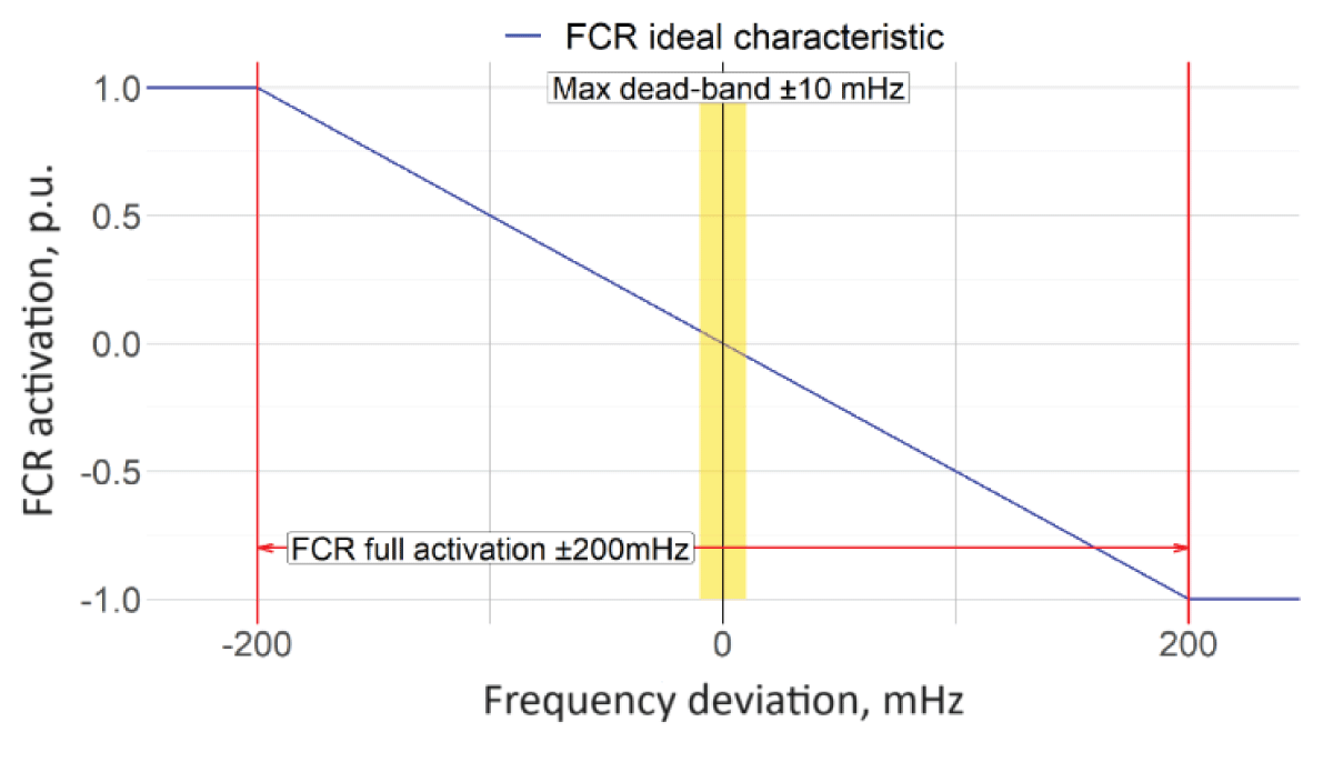
FCR providers deliver their FCR by means of a proportional control reacting to frequency deviations. For generation units the proportional activation is negative–in case of positive frequency deviation, the power output of the FCR provider shall decrease and vice versa. For demand units the proportional activation is positive–in case of positive frequency deviation, the power output of the FCR provider shall increase and vice versa.
The generic activation scheme of a FCR provider is shown in Figure 1. The graph represents on the y-axis the FCR activation (in p.u. of the dimensioned value) and on the x-axis the frequency deviation (mHz) that causes this activation. The curve is intended to be static; it refers to the condition reached once the transient of FCR deployment is completed.
Figure 1: Static frequency deviation/FCR activation example curves.
The provided FCR shall be activated by means of a proportional governor reacting to frequency deviations or alternatively based on a monotonic piecewise linear power–frequency characteristic in the case of relay-activated FCR. It is required that the MW/Hz characteristic curve (FCR activation vs. frequency deviation–e.g. Figure 1) shall be linear or monotonic piecewise linear.
The full activation of the provided FCR shall be reached with a frequency deviation of ±200 mHz. It means that the FCR provided by an FCR provider shall be completely deployed when the frequency deviation of the SA reaches 200 mHz. The positive FCR is deployed with –200mHz, the negative FCR is deployed with +200 mHz.
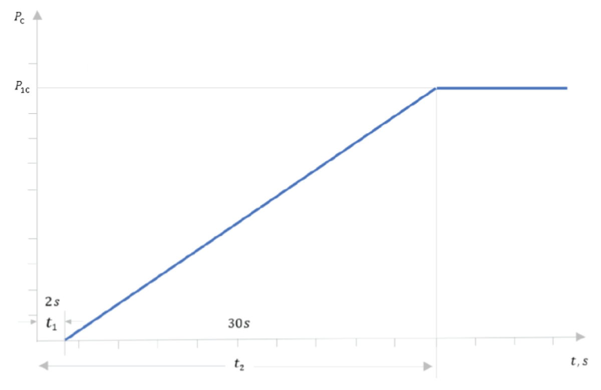
The FCR full activation time is not more than 30 s (t2 in Figure 2). It gives a maximum time for the full activation to be provided. The activation of the FCR by each provider shall begin as soon as possible but no later than 2 s (t1 in Figure 2)
Figure 2: FCR activation curve.
after a frequency deviation. No intentional delay for the activation is allowed. If a provider has a need for a delay in the initial activation of active power frequency response greater than 2 s, it is requested to demonstrate the technical reason for the need.
The FCR activation shall rise linearly or quicker in time. This requirement implies that, as a result of a stepwise frequency deviation, the FCR shall be activated at least linearly in time: it is not acceptable for activation to take place with a function less than linear. As a function:
(1)
Where: t is time; n < 1; k factor. A graphical representation of the formula is provided in Figure 2, which means that in the event of a frequency step change FCR providing unit shall be capable of activating full active power response at or above the line shown in Figure 2.
PC value calculated as follows: PC=𝚫P/Pmax, where Pmax is the maximum capacity to which 𝚫P relates. 𝚫P is the change in active power output from the power–generating module.
The module calculated P1C=P1/max value must provide active power output 𝚫P up to the point 𝚫P1 in accordance with the times t1 and t2, where t1 is the initial delay and t2 is the time for full activation.
The maximum combined effect of the inherent insensitivity of frequency response and the intentional insensitivity provoked by frequency dead–band inserted in the governors of the FCR providing units or FCR providing groups is 10 mHz. It means that the FCR response shall be provided as the frequency deviation exceeds ±10 mHz. The maximum intentional/unintentional dead–band is ±10 mHz.
A potential FCR-providing unit or group of units shall be capable of controlling its active power to a set–point value with a steady–state error not greater than ±10 % of the current FCR activation volume or 0.1 MW, whichever is larger, if not defined differently in the national terms and conditions or other legislation. The frequency measurement used for the frequency control and the determination of the FCR to be provided shall have an accuracy of at least 10 mHz.
The FCR providers that do not rely on energy reservoirs that limit their capability to provide FCR shall activate their FCR for as long as a frequency deviation persists. Generally, there is no maximum time for the provision of FCR. A potential long-lasting unidirectional frequency deviation shall be covered by FCR providers without limitation.
Each FCR provider shall guarantee its FCR contribution for at least the validity period of successful FCR capacity bids with the exception of forced outages. If due to a forced outage, an FCR provider is not able to provide its FCR contribution (even partially) it shall communicate its unavailability to the connecting EPS as soon as possible.
The only exception to this rule is allowed for Limited Energy Reservoir (LER) FCR providers which rely on an energy reservoir that limits their availability. LER FCR providers shall activate their FCR if the frequency deviation persists unless their energy reservoir is exhausted in either the positive or negative direction.
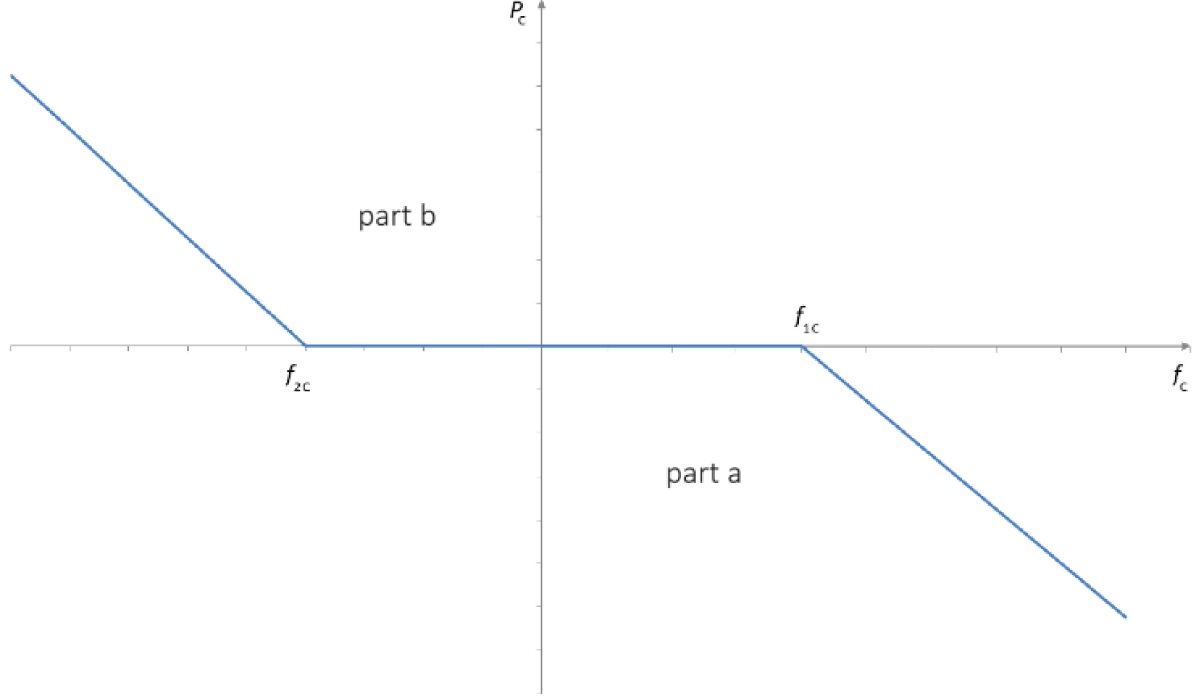
In case of frequency deviations greater than ±200 mHz, a potential FCR provider shall activate considering what follows:
The activation supports the stability of the frequency, adjusting the power output according to the characteristics presented in Figure 3 (part a) for over–frequency transients and Figure 3 (part b) for under–frequency transients. In the Figure 3, the parameters have the following significations:
In Figure 3 (part a) for over–frequency transients:
Figure 3: Frequency support in case of large over/under-frequency transients.
(2)
In Figure 3 (part b) for under–frequency transients:
(3)
Where: d2 and d3 represent the frequency droops, their values shall be set to 5% if not differently instructed by EPS; 𝚫ff represents the frequency variation measured at the CP; 𝚫f1 and 𝚫f2 are the frequency thresholds for the activation of the frequency support, and shall be set to +200 mHz and –200 mHz; fN is the nominal frequency of the system (50 Hz); 𝚫P represents the expected power adjustment for the frequency support.
The active power response shall be provided in addition to the provision of FCR and shall not be intentionally limited below the actual capabilities of the unit;
The power adjustment shall not be intentionally delayed and shall be delivered as fast as feasible without compromising the stability of the unit.
The frequency fC value is calculated as follows: fC=𝚫f/fN and f1C=𝚫f1/fN and f2C=𝚫f2/fN.
Additional requirements for LER FCR providers
An FCR provider is deemed to be an FCR provider with LER in case a full continuous activation of its FCR for a period of 2 hours in either positive or negative direction might, without consideration of the effect of an active Energy Reservoir Management (ERM), leads to a limitation of its capability to provide the full FCR activation due to the depletion of its energy reservoir. ERM controls the State of Charge of the LER FCR provider’s energy reservoir. LER FCR providers that rely on an ERM that limits their FCR availability shall guarantee their FCR contribution without any limitation if the system remains in a normal state. The normal state is a condition in which the system is within operational security limits in the N–situation and after the occurrence of any contingency from a list of contingencies, considering the effect of the available remedial actions [11-13].
Each LER FCR provider shall provide a comprehensive description of the active ERM of the LER FCR provision by providing information on the following points:
1. Full capacity of energy reservoir; 2. Operational limits that affect usage of the reservoir; 3. Operable capacity of the reservoir; 4. Permissible charge/discharge power; 5. Description of planned ERM strategy (energy source used for management); 6. Information on the rate of use of ERM (continuous, each 5 min., etc.); 7. Simulation of ERM operation for 24-hour frequency data); 8. Strategy for operation in alert state and Reserve Mode; 9. Expected BID regularity and size.
As for triggering the alert state and during the alert state, each LER FCR provider shall ensure a continuous FCR full activation for a time period of no less than 30 minutes, defined as Tmin LER of LER FCR providers. The Tmin LER requirement is fulfilled by dimensioning the energy reservoir to meet the minimum requirement. The alert state is a condition in which the system is within operational security limits, but a contingency from a contingency list has been detected and in case of its occurrence the available remedial actions are not sufficient to keep the normal state.
Referring to frequency deviation in CE, an alert state is triggered by one of the two following conditions:
The absolute frequency deviation has continuously exceeded 50 mHz for 15 minutes;
The absolute frequency deviation has continuously exceeded 100 mHz for 5 minutes.
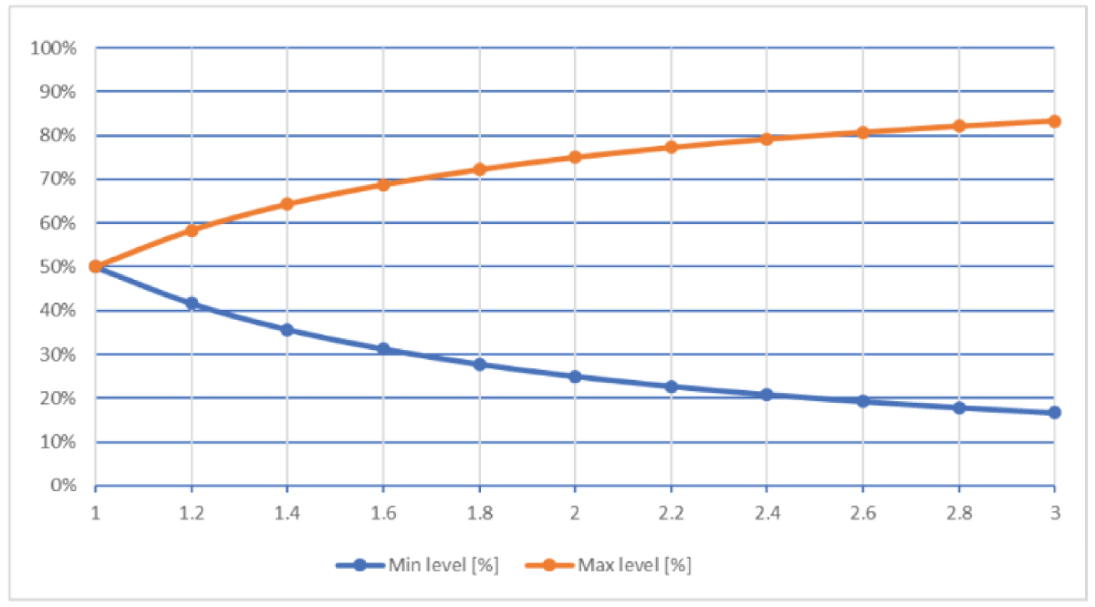
A potential FCR provider with LER shall have an active ERM which can ensure a continuous activation of FCR when the power system is in a normal state according to the SOGL Article 156 [14]. It especially means that, when the power system is in a normal state, the energy reservoir of the FCR providing unit with LER shall be kept within the ranges. The operating range of the reservoir in a normal state is indicated in Figure 4.
Figure 4: Management of the energy reservoir of an FCR-providing unit with LER.
In Figure 4 the y-axis represents the actual level of the reservoir in percent (%) of the usable energy capacity of the reservoir and the x-axis represents the ratio of the usable energy capacity of the reservoir to the prequalified FCR. This is E/PFCR per hour (h).
FCR providers that rely on energy reservoirs that limit their FCR availability LER shall have an active The State of Charge (SoC). management that allows them to ensure a continuous physical activation of FCR in a normal state.
The SoC management is an active operation condition in which the SoC is kept within a level that ensures full activation for a time period of no less than 30 minutes whenever an alert state is triggered. This condition is achieved by the FCR provider operating on the energy market or directly exchanging energy with other plants. The State of Charge SoC management shall not rely on over fulfilment of activation. The activated FCR shall depend only on frequency deviation.
FCR providers with LER shall implement a specific operational status called Reserve Mode (RM). This operation consists of limiting the FCR contribution from LER only to short–term frequency deviations, and not to the mean value.
During a long-lasting frequency deviation, as an LER is approaching the exhaustion condition (reservoir completely full or empty), the RM shall be triggered. The consequence is that the provided FCR is not proportional to frequency deviation anymore. With RM the FCR is proportional only to the short–term frequency deviations, the mean value is not provided anymore.
The LER shall provide only the FCR proportional to the following signal:
(4)
Where: 𝚫f(t) is the frequency deviation at the time t; ta is the full activation time of aFRR of 5 minutes; m (t-ta) is the number of frequency deviation samples within ta.
The FCR contribution associated with the mean value 𝚫f(t)- 𝚫fres(t)) shall be taken over by aFRR.
FCR provision can be provided by technical entities that cannot comply alone with the FCR service technical requirements. To ensure that the FCR provision is possible from these technical entities, FCR service can be provided by FCR-providing groups that can consist of multiple generation, demand, or storage units and/or reserve-providing units. FCR provider shall ensure that the FCR providing group shall have symmetrical capacities available within the FCR providing group.
In case the FCR providing group includes LER FCR providers apply to the FCR reserve proving group as well.
In the presence of technical entities within FCR providing groups activated via a centralized system, it shall be guaranteed that local activation of each technical entity is still possible even in the presence of system split or communication problems. All the units shall implement a decentralized frequency measurement per connection point and the measures shall be made on a local frequency that always ensures an autonomous FCR activation capability.
Furthermore, technical entities within FCR providing groups activated via a centralized system shall be equipped with a functionality aiming at detecting any error in the decentralized system (e.g. loss of communication with decentralized units, failure of the units, etc.). If an error is detected, the provider shall provide the countermeasures needed to ensure the FCR capability.
For each FCR-providing group using a centralized system for frequency assessment, a separate frequency measurement is required to be established to prevent FCR activation malfunction with frequency measurement failure.
In accordance with SOGL Article 154.9, block EPSs allow the use of centralized frequency measurement for FCR groups with a prequalified FCR capacity <= 1.5 MW. If a Balancing Service Provider (BSP) decides to prequalify several FCR groups <= 1.5 MW using centralized frequency measurement, a different frequency meter must be used for each concerned FCR group for redundancy reasons. For any other FCR group, block EPSs require as per product definition local frequency measurement on each delivery point within that FCR group [14-17].
The study has several limitations that should be considered. First, the analysis primarily focused on specific scenarios of EPS disturbances, which may not comprehensively capture the full range of real-world situations. The scope of the study was also limited to certain types of FCR providers, which may affect the generalizability of the findings. Additionally, the study relied on specific simulation tools and parameters, which could introduce bias or limitations in the results. The modeling assumptions, such as the exclusion of certain external factors like extreme weather conditions or unexpected load variations, further limit the applicability of the results to broader contexts.
Future research should aim to expand the scope of the study by incorporating a wider range of scenarios, including those involving different types of FCR providers and varying system conditions. It would also be beneficial to explore the impact of external factors, such as climate-related disturbances, on the stability and reliability of power systems. Additionally, improving the accuracy and comprehensiveness of simulation tools by integrating more dynamic and real-time data could provide more robust results. Collaboration with industry stakeholders to validate the findings with practical case studies and real-world applications would enhance the relevance and applicability of the research.
These enhancements could help bridge the gap between theoretical research and practical implementation, ensuring that the findings are more widely applicable and beneficial for the development of resilient and stable EPSs.
If the BSP meets the requirements of the frequency control parameters and the description of the dynamic parameters and has been performed for FCR service providers with LER: reserve mode activation and control investigations, then the BSP must be issued with technical parameter settings, such as FCR balancing capacity quantities (MW), both for a specific device and for a group of them, which enable the provision of balancing services.
The technical parameters specified for each BSP are valid for the agreed period from the date of the conclusion of the contract. Approval of readiness must be performed repeatedly or anew if the technical or availability indicators of the device change, as well as if there is modernization of equipment related to the activation of the FCR reserve.
If the facility is removed from the FCR-providing group, the EPS must reduce the maximum FCR capacity provided by the FCR-providing group according to the volume of the facility. The FCR quantity for each unit must be submitted with the readiness approval documents. If the volume of a single device cannot be calculated or estimated, and if the device has a significant impact on the quality assurance of the FCR service, then the device group providing the FCR service needs to retest the readiness assertion to determine the new and maximum amount of FCR capacity of the providing group.
Deltuva R, Kriuglaitė M, Otas K. Compatibility Analysis of Frequency Containment Reserve and Load Frequency Control Functions. IgMin Res. August 14, 2024; 2(8): 712-719. IgMin ID: igmin237; DOI: 10.61927/igmin237; Available at: igmin.link/p237
Address Correspondence: Ramūnas Deltuva, Department of Electrical Engineering, Kaunas University of Technology, Studentu St. 48–236A, Kaunas, Lithuania, Email: [email protected]
How to cite this article: Deltuva R, Kriuglaitė M, Otas K. Compatibility Analysis of Frequency Containment Reserve and Load Frequency Control Functions. IgMin Res. August 14, 2024; 2(8): 712-719. IgMin ID: igmin237; DOI: 10.61927/igmin237; Available at: igmin.link/p237


 スキャンしてリンクを取得