Welcome to IgMin Research – an Open Access journal uniting Biology, Medicine, and Engineering. We’re dedicated to advancing global knowledge and fostering collaboration across scientific fields.
At IgMin Research, we bridge the frontiers of Biology, Medicine, and Engineering to foster interdisciplinary innovation. Our expanded scope now embraces a wide spectrum of scientific disciplines, empowering global researchers to explore, contribute, and collaborate through open access.
Welcome to IgMin, a leading platform dedicated to enhancing knowledge dissemination and professional growth across multiple fields of science, technology, and the humanities. We believe in the power of open access, collaboration, and innovation. Our goal is to provide individuals and organizations with the tools they need to succeed in the global knowledge economy.
IgMin Publications Inc., Suite 102, West Hartford, CT - 06110, USA
An experimental investigation was carried out to study the effect of circular cross-holes on the failure behavior of unidirectional glass fiber reinforced with unsaturated polyester resin composites, varying cross-ply laminates that were subjected to axial tensile load. This paper deals with the effects of the circular notch and the number of plies on nominal tensile and net tensile strengths. Tensile strengths were investigated for composites with cross-ply([0/90]. [90°/0°/90°] and [0°/90°/0°].90°), orientation and varying the laminate layers with a central hole, and effects of volume fraction and number of ply on mechanical properties for un-notched (smooth) and notched specimens were also studied. The results showed that increasing the number of plies has a marginal effect on tensile strength values. The fraction of volume has significant effects and for increasing the number of plies about 9% decreases in nominal tensile strength and about 11% decrease in the net tensile strength was observed. The same results were obtained with finite element analysis.
In recent years there has been a focus on new composite materials because of their dimensional stability and superior mechanical and manufacturing properties as well as interest in the use of natural fibers as reinforcement in Polymer Matrix Composites (PMCs). The glass fiber laminates [1] were manufactured using unidirectional glass/epoxy prepreg obtained by infusing E-Glass-300 fibers with 46 vol% bisphenol A epoxy resin (Advanced Composites Group, United Kingdom).
Utilization of composite materials in advanced lightweight structures has considerable benefits for modern industry [2,3]. Nowadays, Composite laminates structure has competitive advantages in many industrial applications for aircraft, aerospace, and marinas [4] Botelho, et al. [5] developed a Fiber/Metal Laminate with light weight to improve the mechanical properties; they found that a new composite has low moisture absorption availability than other composites as conventional carbon fiber/epoxy, so, many companies use this new composite in modern manufacturing [5].
For design, accurate calculations must be considered for composite material properties such as shear modulus, strength, and ultimate strain [2]. Many experimental methods are available for evaluating shear properties such as V-notch beam test [6]. Khashaba [7] carried out a study of tensile strength, modulus, and Poisson’s ratio for cross-ply composite laminates that were made with different angles of the axis (0°, 15°, 30°, 45°, 60°, 75°, and 90°). Liu, et al. [8] illustrated the composite laminates’ response under shear loading for different plies thicknesses and ply orientation. Failure of material refers to complete loss in load-carrying capacity; this is a result of gradual material stiffness degradation. Different failure modes must be considered as tension fiber rupture, compression fiber buckling, and kinking, matrix cracking under transverse shearing and tension, and matrix crushing under transverse shearing and compression [8]. Hashin and others [9-13] suggested a continuum-based criteria that predicted different failure modes. J.L.Y. Tan, et al. carried out notches and un-notched cross-ply laminates test where damage effects were profound for specimens [14]. B.G. Green, et al. investigated hole diameter, ply, and laminate thickness as independent variables, but, keeping hole diameter/width and length ratio constant. B.G. Green’s results showed that increasing specimen size leads to an increase in strength with a maximum reduction reach of 64%, so, damage propagated can be controlled by a controlled ply thickness/hole diameter ratio [15].
The effect of various stacking sequences on the mechanical properties of natural and glass fiber hybrid composites was investigated and found that the stacking sequence contributes to delayed composite failure by improving the interlaminar shear strength, fracture toughness, and tensile strength [16,17]. The investigation also concluded that the alternate stacking sequence is the best option [18-20]. Among synthetic fibers, GFRP is common in use as compared with other synthetic fibers such as aramid and carbon because it has a lower cost and a lot of suitable properties for different applications. In modern industries as aircraft structures, mechanical fastening as bolted joints remains the joining method for composite components, so drilled holes are carried out in structures for these joints, but, the efficiency of this method is not completely perfect because of the reduction in fracture strength due to stress concentration around these holes, and this causes a reduction in notched tensile and compressive strength of a composite laminate. Under stress concentrations, experimental studies showed that damages around such regions include ply cracks, splits, and delamination [21-25].
The main objective of the present work is to investigate the effects of opened holes on tensile/failure behaviors of glass fiber reinforced polyester (GFRP) cross-ply with stacking laminates that were subjected to axial tensile stresses. This work deals with the effects of open hole notch and the number of plies on nominal tensile and net tensile strengths.
Experimental work
The mechanical behavior of composite materials for unnotched (smooth) and notched specimens was tested subjected to axial tensile load. The effect of the number of cross plies, volume friction (Vf), and orientation of the reinforced material was also tested. Three different test samples were manufactured by the handle-up process as follows: 2s (4 layers) with Vf = 40%, 3s (6 layers) with Vf = 45%, and 4s (8 layers) with Vf = 42%.
Used materials and tools: Before the lamination process glass fiber was allowed to equilibrate under ambient conditions of Relative Humidity (RH) and temperature. Fiber volume fractions (Vf) were adjusted by varying the weight of fiber used in the initial hand lay-up. Wooden mold was used as a container and fiber wires were used as an essential component for the required composite. Wax (Gruber care manufactured by “Gruber System” company) was used for mold coating and a resin mixture was used to fill the mold. Iron roller was used for air evacuation and a water-cooled diamond saw was used to cut specimens in required sample sizes. Rectangular aluminum strips were used at the ends of the specimen to save specimens through tests. To examine the tensile properties of the fiber polyester composite, a universal testing machine INSTRON 3382 as per ASTM D3039-08 [26] was used with a loading capacity of up to 100 KN and an accuracy of 0.05%.
Specimens preparation: 600* 600 mm sheets were prepared by hand lay-up technique with the aid of molds to get smooth-sided surfaces. Mold has screws that be fixed around mold edges, and fiber wires are tied between these screws. Mold is filled with the required materials. The entire mold surface was coated with wax by a brush and allowed to dry at room temperature. A 250*500 mm rectangular Fibre-glass (E-glass “M 706” 450 gm/cm2 that had been manufactured by “European Owens Coring Fibre-glass S.A.” company. ) was cut of 4, 6 and 8 layers with cross-ply such as [0/90]s, [0/90/0]s, and [0/90/0/90]s. Volume fraction (%), layer arrangement, and orientation ratio are shown in Table 1.
Table 1: Plyorientation and stacking ratio of composite.
Number of Layers
Volume of Fraction(%)
Layer Arrangement 0- Degree (Symmetrical (s))
90- Degree
0/90 Ratio
4
40
(00,900)s
2
2
1:1
6
45
(00,900, 00)s
4
2
2:1
8
42
(00,900,00,900)s
4
4
1:1
About 400 gm of resin was mixed with 92 gm of its hardener “HY5138” manufactured by “Vantico company” (mixing ratio as given by producer is 100: 23 of weights) and was stirred well at room temperature. The entire mold surface was painted with a resin mixture by a brush, and a laminate layer of fiberglass was laid down per the proposed layer composition. Air was evacuated by well pressing with an iron roller, after stacking the arrangement of fiber layers resin-hardner mixture in molten form was poured into the mold and left to cure for 24 hours at standard ambient temperature and pressure. For each sample, the same process was repeated, and the mold was also covered with a lid to get a regular and smooth surface. Thereafter, sample mold and equipment were cleaned with acetone [26-28].
For the preparation of the composite samples, it is assumed that the fiber acts as longitudinal cross-ply segments that individually behave in a linear-elastic manner, embedded in a matrix (mixture of polyester resin and harden) which itself is assumed to be linear-elastic, it is possible to describe the deformation behavior of the composite using a Cox-type shear lag model equation [29] presents the theoretical elastic stress-strain relationship before the onset of yielding.
(1)
Where n is given by:
And where: s1 is the composite tensile stress, e1 is the composite tensile strain, vm is the matrix Poisson’s ratio and assumed to be 0.35 *29], and E Efs is the Young’s modulus of the fiber segment. Assuming that Efs is the modulus of the glass fiber free from defects, or fiber has all defects “pulled out”, and is taken to be 90 Gpa [30]. It is possible to construct theoretical stress-strain curves for different values of s, the segment aspect ratio.
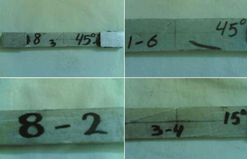
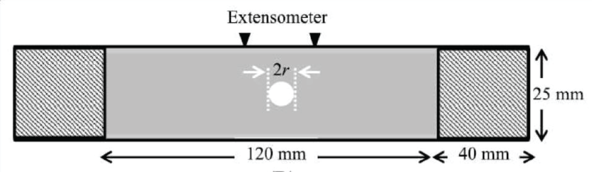
Carefully, 200 *25 mm with proposed layer thickness notched and unnotched tensile specimens were cut according to ASTM standards by using a water-cooled diamond saw. The specimen width and thickness were measured to an accuracy of 0.01 mm with a digital micrometer, from which the cross-sectional area was calculated. A strip of 40 *25 *2 mm rectangular aluminum sheet (tabs) was bonded with an epoxy-based adhesive film, VTA 260/PK13-313 (Cytec Industrial Materials, United Kingdom) to specimen ends. These tabs reduce the stress concentration of serrated grips on specimens and prevent them from slippage. Also, end tabs transfer the lateral operational compressive load of grips and prevent specimen crushing between grips. Before the bonding process, the aluminum tabs’ surface had been roughed by abrasive paper with a fine grade. Figure 1 represents a specimen with rectangular aluminum ends, and the tested samples are shown in Figure 2. After mold filling, it must be left for 12 hours under pressure. The black arrows on the specimens from the top (25 mm apart) indicate the contact points for the extensometer while the hatched rectangular strips located at the end are aluminum strips.
Figure 1: The tensile properties for unnotched and open-hole Glass fiber laminate composites.
Figure 2: Samples with varying crossly laminated layer.
Tensile test
Tensile test specimen were prepared according to (ISO 638-02). Jaws were tightening evenly and firmly to prevent slippage of specimen during test and to avoid a specimen crushing. Operating machine program was adjusted to carry out the test under a standard cross head speed 7 mm/min (Table 2).
Table 2: The tensile properties for unnotched and open-hole Glass fiber laminate composites.
Nominal fail- Composite 2r (mm) Diameter width ratio E ure stress Strain ? f(%)
ASTM testing standards were followed to make open-hole tension specimens produced by introducing centrally located blunt circular holes using high-strength steel drill bits with varying diameters (2.5,5 and 7.5 mm) as illustrated in Figure 1. The tensile properties for notched open-hole glass fiber reinforced polyester composite with varying cross-ply laminates are illustrated in Table 2.
To observe shear damage clearly, cross-ply-laminated GFRP were prepared by changing the orientation of the fiber where normally central notches are introduced along the fiber axis in unidirectional in which shear damage may easily expose from notch roots in a parallel direction to fibers due to extremely low shear strength. Based on this concept, notched specimens with various 0/90 layer ratios were fractured, and shear damage in these specimens was observed.
Effect of notch and number of ply on nominal tensile strength
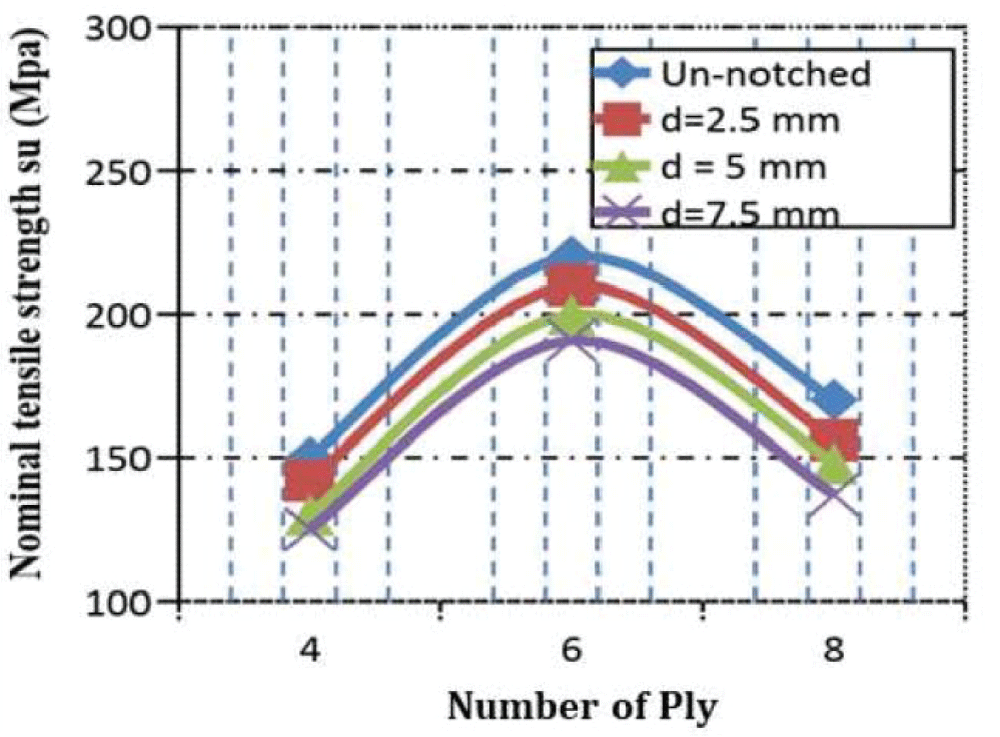
Normally tensile strength (s) is calculated as the Ultimate tensile load (F) upon effective cross-sectional area (Ao). To observe the shear damage subjected to tensile load by varying the number of plies and notch size is shown in Figure 3.
Figure 3: Plies number effects on nominal tensile strength/different hole diameters.
It was observed that centrally created notch size and orientation of the cross-plies with varying numbers of layers have a significant effect on tensile strength. Unnotched specimens have the highest nominal tensile strength of 238 MPa. An unnotched specimen does not have any weaknesses actual glass fiber has a higher value as reported in [29] matrix material makes it weaker as well and notching leads to weakness in any solid body as a result of voids in bonding between its particles surrounded by notch, tear under loads starts from hole peripheral edges. It has been also observed that notch size also affects the material mechanical properties notch size 7.5 diameter has a minimum tensile strength of 188 MPa. Notch size is relevant to the lateral size of the sample it is important to analyze the tensile behavior with a diameter-width ratio.
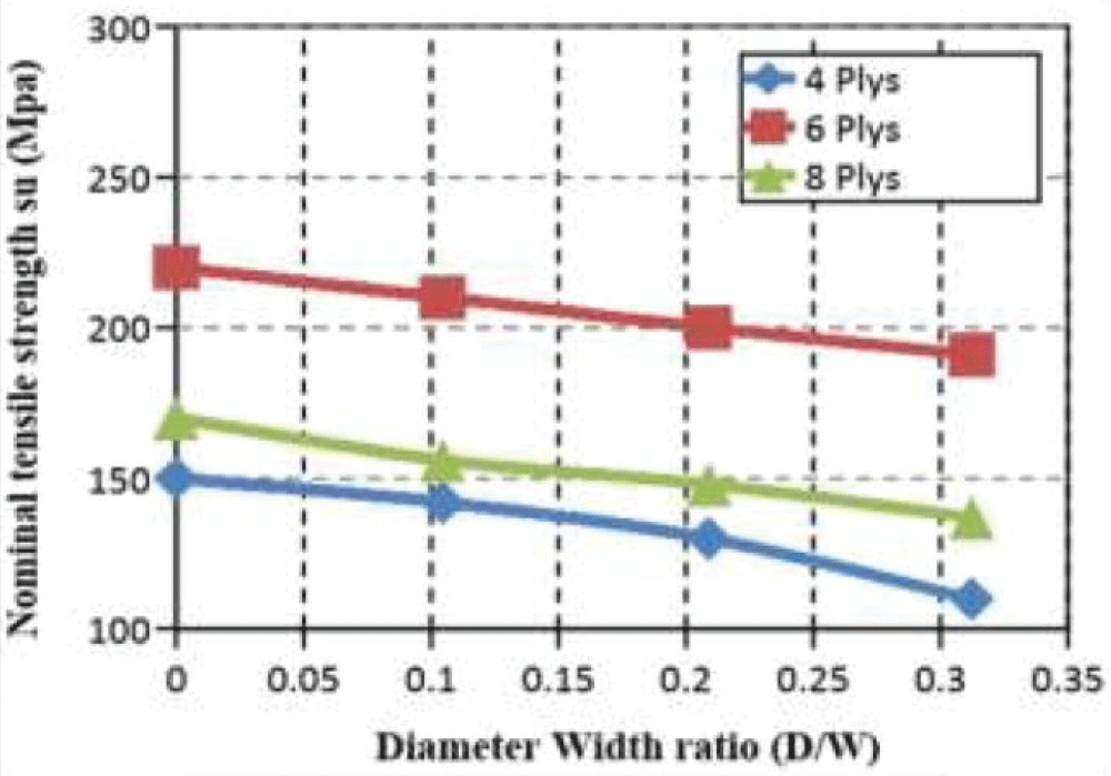
Figure 4 presents the diameter-width ratio for various cross-ply layer composition and fiber orientation.
Figure 4: Tensile strength vs diameter-width ratio with varying cross-plys
From this experiment, it was observed that the increase in diameter width ratio leads to a decrease in nominal tensile strength because of the decrease in solid size along the edges of the drilled hole and width of the specimen. Edge creates a weakness in bonding so, the resistance of specimen particles decreases and the risk of mechanical cracking will be higher by increasing the diameter-width ratio. It has been observed that tensile strength does not depend upon on number of plies, results reveal that nominal tensile strength for 6-ply is more than that for 4-ply and 8-ply cases, and this can be related to the high volume fraction of fiber for 6-ply specimens. Based on Figure (4), curves have almost the same slope which means the decreasing rate in nominal tensile strength is linear with a diameter-width ratio. For example, for a 2.5 mm hole diameter, it can be noted that about a 9% decrease in strength for all numbers of plies.
The maximum Volume friction is about 45 % Average Young’s modulus of the effective 6 – 6-layer composite (Ec) was detected as 39.0 ± 0.2 GPA. The rule of mixture relationship [29] was taken into account as shown in equation (2).
(2)
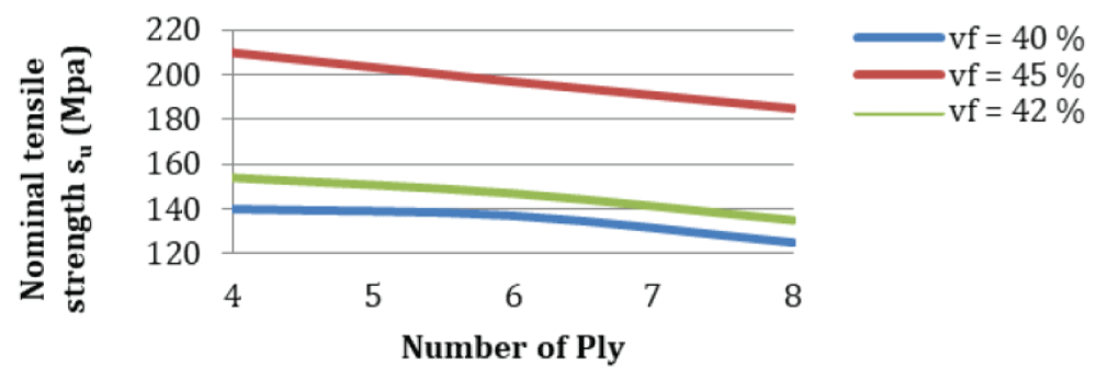
Where Ec is the composite, Vf is the fiber, and Em = 4.7 GPa [29] is the matrix material Young; ‘s modulus. Figure 5 illustrates the effect of fiber volume fraction (Vf) on nominal tensile strength values with varying cross-ply numbers, A Percentile increase in volume fraction leads to an increase in nominal tensile strength, this reveals the fiber’s importance where they represent a reinforced power for the specimen body.
Figure 5: Fiber volume friction affects normal tensile strength with varying numbers of plies.
Based on results from Figure 5 tensile strength is decreasing with an increase in several plies for different fiber volume fractions.
Effect of notch size and number of plies on net tensile strength
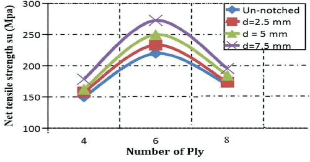
To consider the net tensile effect cross-section area under consideration was taken into account as An = (Ls – d) × t where: “ An “ is the net cross-section area (net area), “t” is the specimen thickness, “ Ls “ is the solid part length that can be calculated as “specimen width and “d” hole diameter”. Net tensile strength (sn) is considered by selecting the net effective cross-section area. The influence of several plies on net strength for different hole sizes can be illustrated in Figure 6. For example, for a 5 mm hole in diameter, it can be noticed that tensile strength is increased by about 11% for different cross-ply values.
Figure 6 reveals that net tensile strength is increased with increasing the hole diameter for all different plies. The un-notched specimen has the lowest values for net tensile strength because of the large value of the specimen’s effective cross-section area. For 7.5 diameter, the value of effective cross-section will be small, so, it has the largest value of net tensile strength of 270 MPs.
Figure 6: Effect of number of plies on net tensile strength on varying notch size.
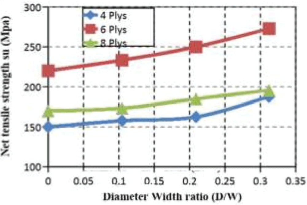
Results of Figure 7 show that net tensile strengths are increased with increasing diameter-width ratio for all values of cross-ply layers. For these cases, the net area will be decreased as a result of a decrease in the solid part area. Figure 8 reveals that a composite with 6 plies showed the highest values of net tensile strength for all diameter-width ratios, this means that the increasing number of plies will not increase the value of the net tensile effect.
Figure 7: Diameter-width ratio effect on net tensile strength.
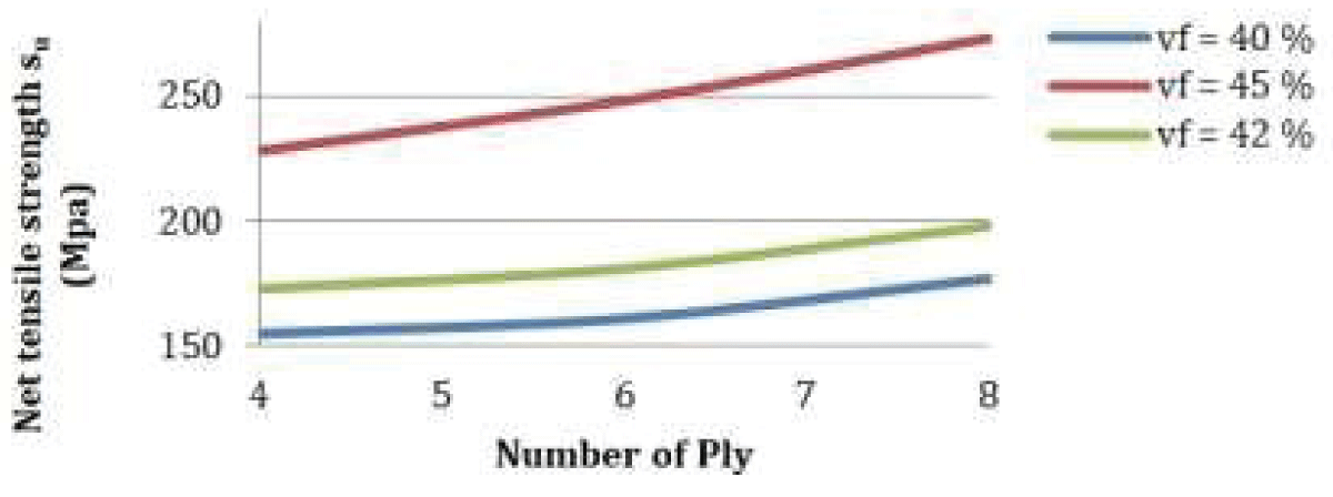
The effect of fraction volume (Vf) of reinforced glass fiber in composition with polyester resin (matrix material) was also tested as shown in Figure 8, net tensile strength value was increased with increasing in several ply for different fiber volume fractions.
Figure 8: Effect of fraction volume on net tensile strength with varying number of plies.
Finally, experiments reveal that increasing in number of plies has no significant effect on tensile strength values, but orientation cross-ply and volume fraction (Vf) have vital effects for example, 6-ply (laminate) of all cases has the maximum value of tensile strength, and so, this leads to more load carrying capability than other tested number of plies and volume.
Finite element method
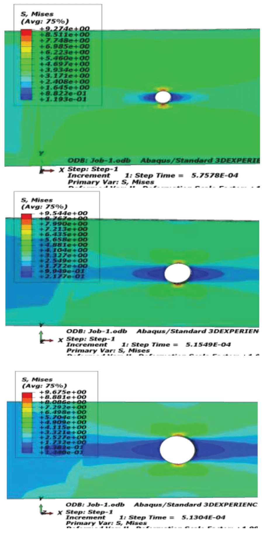
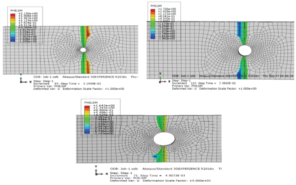
Fracture mechanics techniques are widely used for crack propagation prediction in structures. Material fracture modeling is an important application for material cracks, The Finite element method is a common tool used for crack propagation analysis and, the reliability of elastic fracture mechanics for specimens that are exposed to tensile loading [30]. In this work, a rectangular strip with a crack emanating from a diameter hole under tensile loading has been analyzed with different diameters. Crack propagation is considered on crack emanating from a diameter hole. Figure 9 shows the maximum principal stress distribution for the final step of the crack propagation. Stress distribution is symmetric and the higher stress is concentrated at the lateral surrounding of the hole.
Figure 9: a-D = 2.5mm, D = 5mm, D = 7 mm, Crack growth path with different hole diameters.
Finite element statistics were compared with the finite element method [31], and the result seems very close.
Figures 10 illustrate the results for different diameters.
Figure 10: a-D = 2.5 mm, b-D = 5 mm, c-D = 7 mm. The von Mises contour stress with different hole diameters.
This work investigates the effects of fraction volume and number of plies in mechanical properties of glass fiber reinforced polyester composite for unnotched (smooth) and notched specimens. Experimental results showed that increasing in several plies has no vital effect on tensile strength values, but an arrangement of these ply and fraction of volume has essential effects and 6-ply (laminate) of all cases proves this result.
The highest value of nominal strength is achieved for smooth specimens.
After analyzing the data it can be predicted from the data graphs the linear behavior of the nominal and net tensile strength for different open hole sizes and number of cross ply laminates and its orientation.
For the effect of notch size and number of plies on nominal tensile strength, nominal strengths of all specimens are linearly decreased with increasing of hole diameter width ratio, thus decreasing load-carrying capability. About a 9% reduction in nominal tensile strength for all numbers of cross-ply laminates was observed.
For the effect of notch size and number of cross-ply laminates on net tensile strength, it has been observed that net tensile strength for all specimens increased linearly with increasing diameter-width ratio for cross-ply laminates. About 11% improvement in net tensile strength for all numbers of cross-ply laminates was recorded.
For the effect of volume fraction on tensile strength for different numbers of cross-ply laminates and open hole diameter–width ratio, nominal tensile strength curves tend to increase when the number of cross-ply laminates is increased, but, net tensile strength curves tend to decrease when the number of cross-ply laminates was increased.
For finite element analysis strategy and comparing with obtained results by current studies, it’s seen that are very close.
Totry E, Gonzalez C, Llorca J. Mechanical behavior of composite materials in shear: experiments and simulations. Anales de Mecánica de la Fractura. 2009;1:187-192.
Iwamoto M, Ni Q-Q, Fujiwara T, Kurashiki K. Intralaminar fracture mechanism in unidirectional CFRP composites. Eng Fract Mech. 1999;64:721-745.
Tan W, Falzon BG, Price M, Liu H. The role of material characterization in the crush modeling of thermoplastic composite structures. Compos Struct. 2016;153:914-927.
Abdellah MY, Kamal MQ, Alsoufi MS, Ghazaly NM, Abdel-Jaber GT. Mechanical properties of lab joint composite structure of glass fiber reinforced polymers. Mater Sci Appl. 2017;8:553-565.
Botelho EC, Silva RA, Pardini LC, Rezende MC. A review on the development and properties of continuous fiber/epoxy/aluminum hybrid composites for aircraft structures. Mater Res. 2006;9(3):1-12.
American Society for Testing and Materials. ASTM D4255 / D4255M - 01. Standard Test Method for In-Plane Shear Properties of Polymer Matrix Composite Materials by the Rail Shear Method. West Conshohocken, PA: ASTM; 2001.
Khashaba UA. In-plane shear properties of cross-ply composite laminates with different off-axis angles. Compos Struct. 2004;65(2):167-177.
Lee H. Damage modelling for composite structures. [PhD thesis]. Manchester: University of Manchester; 2015.
Liu H, Falzon BG, Catalanotti G. Studies on the effects of laminate thickness and orientation on the shear response of composite laminates. In: Proceedings of the 21st International Conference on Composite Materials; 2017 Aug 20–25; Xi’an.
Hashin Z. Failure criteria for unidirectional fiber composites. ASME J Appl Mech. 1980;47:329-334.
Hashin Z, Rotem A. A fatigue failure criterion for fiber reinforced materials. J Compos Mater. 1973;7:448-464.
Sun CT, Quinn BJ, Oplinger DW. Comparative evaluation of failure analysis methods for composite laminates. DOT/FAA/AR-95/109. 1996.
Puck A, Schurmann H. Failure analysis of FRP laminates by means of physically based phenomenological models. Compos Sci Technol. 1998;58:1045-1067.
Puck A, Schurmann H. Failure analysis of FRP laminates by means of physically based phenomenological models. Compos Sci Technol. 2002;62:1633-1662.
Green BG, Wisnom MR, Hallett SR. An experimental investigation into the tensile strength scaling of notched composites. Compos Part A Appl Sci Manuf. 2007;38(3):867-878.
Zhang Y, Li Y, Ma H, Yu T. Tensile and interfacial properties of unidirectional flax/glass fiber reinforced hybrid composites. Compos Sci Technol. 2013;88:172-177.
Aabdul Khalil HPS, Kang CW, Khairul A, Ramli R, Adawi TO. The effect of different laminations on mechanical and physical properties of hybrid composites. J Reinf Plast Compos. 2009;28:1123-1137.
Amico SC, Angrizani CC, Drummond ML. Influence of the stacking sequence on the mechanical properties of glass/sisal hybrid composites. J Reinf Plast Compos. 2010;29:179-189.
Chandrasekar M, Siva T, Senthil Muthu Kumar K, Senthilkumar K, Siengchin S, Rajini N. Influence of fibre inter-ply orientation on the mechanical and free vibration properties of banana fibre reinforced polyester composite laminates. J Polym Environ. 2020;28:2789-800.
Lin Feng N, Dhar Malingam S, Subramaniam K, Selamat M, Juan W. The investigation of the tensile and quasi-static indentation properties of pineapple leaf/Kevlar fibre reinforced hybrid composites. Def S T Tech Bull. 2020;13:117-129.
Tan JLY, Fleck N, Deshpande VS, Kashiwagi M. Investigating the damage mechanisms and their effects on the notch sensitivities of cross-ply CFRP laminates under uniaxial loading. In: ECCM16 – 16th European Conference on Composite Materials; 2014 Jun 22–26; Seville, Spain.
Sallam HEM. Effect of a circular hole on static and fatigue strength of unidirectional carbon-fiber/epoxy plate. Submitted to: 10th ICSG, Tenth International Colloquium on Structural and Geotechnical Engineering; 2003 Apr 22–24; Cairo, Egypt.
Tang HC, Nguyen T, Chuang T, Chin J, Lesko J, Wu HF. Fatigue model for fiber-reinforced polymeric composites. J Mater Civil Eng. 2000;12:97-104.
Whitworth HA, Mahase H. Failure of orthotropic plates containing a circular opening. Compos Struct. 1999;46:53-57.
Gourichon B, Deléglise M, Binetruy C, Krawczak P. Dynamic void content prediction during radial injection in liquid composite molding. Compos Part A Appl Sci Manuf. 2008;39:46-55.
Laksimi A, Gong XL, Benzeggagh ML. Analysis of damage mechanisms in a centrally notched glass-fiber/epoxy plate. Compos Sci Technol. 1994;52:85-91.
Kang TJ, Lee KW. Strength prediction for mechanical joints in the laminated composite plate using progressive failure analysis. Polym Polym Compos. 1997;5:343-351.
Hull D, Clyne TW. An introduction to composite materials. Cambridge: Cambridge University Press; 1996.
Baley C. Analysis of the flax fibres tensile behavior and analysis of the tensile stiffness increase. Compos Part A. 2002;33:939-948.
Tankasala HC, Deshpande VS, Fleck NA. Notch sensitivity of orthotropic solids: interaction of tensile and shear damage zones. Int J Fract. 2018;212:123-142.
Eladawi AE. The Effect of Stacking Sequence and Ply Orientation with Central Hole on Tensile Behavior of Glass Fiber-polyester Composite. IgMin Res. July 15, 2024; 2(7): 578-584. IgMin ID: igmin221; DOI: 10.61927/igmin221; Available at: igmin.link/p221
Address Correspondence: Ahmad E Eladawi, Department of Mechanical Engineering, Benha University, Banha, Egypt, Email: [email protected]
How to cite this article: Eladawi AE. The Effect of Stacking Sequence and Ply Orientation with Central Hole on Tensile Behavior of Glass Fiber-polyester Composite. IgMin Res. July 15, 2024; 2(7): 578-584. IgMin ID: igmin221; DOI: 10.61927/igmin221; Available at: igmin.link/p221
Figure 1: The tensile properties for unnotched and open-hole...
Figure 2: Samples with varying crossly laminated layer....
Figure 3: Plies number effects on nominal tensile strength/d...
Figure 4: Tensile strength vs diameter-width ratio with vary...
Figure 5: Fiber volume friction affects normal tensile stren...
Figure 6: Effect of number of plies on net tensile strength ...
Figure 7: Diameter-width ratio effect on net tensile strengt...
Figure 8: Effect of fraction volume on net tensile strength ...
Figure 9: a-D = 2.5mm, D = 5mm, D = 7 mm, Crack growth path ...
Figure 10: a-D = 2.5 mm, b-D = 5 mm, c-D = 7 mm. The von Mise...
Totry E, Gonzalez C, Llorca J. Mechanical behavior of composite materials in shear: experiments and simulations. Anales de Mecánica de la Fractura. 2009;1:187-192.
Iwamoto M, Ni Q-Q, Fujiwara T, Kurashiki K. Intralaminar fracture mechanism in unidirectional CFRP composites. Eng Fract Mech. 1999;64:721-745.
Tan W, Falzon BG, Price M, Liu H. The role of material characterization in the crush modeling of thermoplastic composite structures. Compos Struct. 2016;153:914-927.
Abdellah MY, Kamal MQ, Alsoufi MS, Ghazaly NM, Abdel-Jaber GT. Mechanical properties of lab joint composite structure of glass fiber reinforced polymers. Mater Sci Appl. 2017;8:553-565.
Botelho EC, Silva RA, Pardini LC, Rezende MC. A review on the development and properties of continuous fiber/epoxy/aluminum hybrid composites for aircraft structures. Mater Res. 2006;9(3):1-12.
American Society for Testing and Materials. ASTM D4255 / D4255M - 01. Standard Test Method for In-Plane Shear Properties of Polymer Matrix Composite Materials by the Rail Shear Method. West Conshohocken, PA: ASTM; 2001.
Khashaba UA. In-plane shear properties of cross-ply composite laminates with different off-axis angles. Compos Struct. 2004;65(2):167-177.
Lee H. Damage modelling for composite structures. [PhD thesis]. Manchester: University of Manchester; 2015.
Liu H, Falzon BG, Catalanotti G. Studies on the effects of laminate thickness and orientation on the shear response of composite laminates. In: Proceedings of the 21st International Conference on Composite Materials; 2017 Aug 20–25; Xi’an.
Hashin Z. Failure criteria for unidirectional fiber composites. ASME J Appl Mech. 1980;47:329-334.
Hashin Z, Rotem A. A fatigue failure criterion for fiber reinforced materials. J Compos Mater. 1973;7:448-464.
Sun CT, Quinn BJ, Oplinger DW. Comparative evaluation of failure analysis methods for composite laminates. DOT/FAA/AR-95/109. 1996.
Puck A, Schurmann H. Failure analysis of FRP laminates by means of physically based phenomenological models. Compos Sci Technol. 1998;58:1045-1067.
Puck A, Schurmann H. Failure analysis of FRP laminates by means of physically based phenomenological models. Compos Sci Technol. 2002;62:1633-1662.
Green BG, Wisnom MR, Hallett SR. An experimental investigation into the tensile strength scaling of notched composites. Compos Part A Appl Sci Manuf. 2007;38(3):867-878.
Zhang Y, Li Y, Ma H, Yu T. Tensile and interfacial properties of unidirectional flax/glass fiber reinforced hybrid composites. Compos Sci Technol. 2013;88:172-177.
Aabdul Khalil HPS, Kang CW, Khairul A, Ramli R, Adawi TO. The effect of different laminations on mechanical and physical properties of hybrid composites. J Reinf Plast Compos. 2009;28:1123-1137.
Amico SC, Angrizani CC, Drummond ML. Influence of the stacking sequence on the mechanical properties of glass/sisal hybrid composites. J Reinf Plast Compos. 2010;29:179-189.
Chandrasekar M, Siva T, Senthil Muthu Kumar K, Senthilkumar K, Siengchin S, Rajini N. Influence of fibre inter-ply orientation on the mechanical and free vibration properties of banana fibre reinforced polyester composite laminates. J Polym Environ. 2020;28:2789-800.
Lin Feng N, Dhar Malingam S, Subramaniam K, Selamat M, Juan W. The investigation of the tensile and quasi-static indentation properties of pineapple leaf/Kevlar fibre reinforced hybrid composites. Def S T Tech Bull. 2020;13:117-129.
Tan JLY, Fleck N, Deshpande VS, Kashiwagi M. Investigating the damage mechanisms and their effects on the notch sensitivities of cross-ply CFRP laminates under uniaxial loading. In: ECCM16 – 16th European Conference on Composite Materials; 2014 Jun 22–26; Seville, Spain.
Sallam HEM. Effect of a circular hole on static and fatigue strength of unidirectional carbon-fiber/epoxy plate. Submitted to: 10th ICSG, Tenth International Colloquium on Structural and Geotechnical Engineering; 2003 Apr 22–24; Cairo, Egypt.
Tang HC, Nguyen T, Chuang T, Chin J, Lesko J, Wu HF. Fatigue model for fiber-reinforced polymeric composites. J Mater Civil Eng. 2000;12:97-104.
Whitworth HA, Mahase H. Failure of orthotropic plates containing a circular opening. Compos Struct. 1999;46:53-57.
Gourichon B, Deléglise M, Binetruy C, Krawczak P. Dynamic void content prediction during radial injection in liquid composite molding. Compos Part A Appl Sci Manuf. 2008;39:46-55.
Laksimi A, Gong XL, Benzeggagh ML. Analysis of damage mechanisms in a centrally notched glass-fiber/epoxy plate. Compos Sci Technol. 1994;52:85-91.
Kang TJ, Lee KW. Strength prediction for mechanical joints in the laminated composite plate using progressive failure analysis. Polym Polym Compos. 1997;5:343-351.
Hull D, Clyne TW. An introduction to composite materials. Cambridge: Cambridge University Press; 1996.
Baley C. Analysis of the flax fibres tensile behavior and analysis of the tensile stiffness increase. Compos Part A. 2002;33:939-948.
Tankasala HC, Deshpande VS, Fleck NA. Notch sensitivity of orthotropic solids: interaction of tensile and shear damage zones. Int J Fract. 2018;212:123-142.


 スキャンしてリンクを取得