Welcome to IgMin Research – an Open Access journal uniting Biology, Medicine, and Engineering. We’re dedicated to advancing global knowledge and fostering collaboration across scientific fields.
At IgMin Research, we bridge the frontiers of Biology, Medicine, and Engineering to foster interdisciplinary innovation. Our expanded scope now embraces a wide spectrum of scientific disciplines, empowering global researchers to explore, contribute, and collaborate through open access.
Welcome to IgMin, a leading platform dedicated to enhancing knowledge dissemination and professional growth across multiple fields of science, technology, and the humanities. We believe in the power of open access, collaboration, and innovation. Our goal is to provide individuals and organizations with the tools they need to succeed in the global knowledge economy.
IgMin Publications Inc., Suite 102, West Hartford, CT - 06110, USA
The proper geometry of belt splices influences their subsequent performance and durability during operation. Despite being such a critical aspect, evaluating the geometry of splices can be challenging, especially after their fabrication and vulcanization. This article presents an approach to diagnosing the geometry of belt splices based on the examination of belts using the DiagBelt+ magnetic system. Through the analysis of practical applications and the benefits derived from monitoring splice geometry, the article emphasizes the importance of diagnosing the geometry of belt splices to improve their quality and performance.
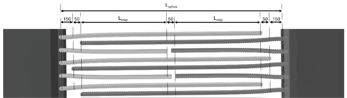
To ensure the highest possible quality of belt splices, which constitute an essential and simultaneously the weakest element of conveyor belt loops [11Lodewijsk G. Applied belt splices design. Conference: SafeCon 1At: Johannesburg, South Africa, 2014.-33Temerzhanov A, Stolpovskikh I, Sładkowski A. Analysis of reliability parameters of conveyor belt joints. Transp Probl. 2012; 7.], the technology of making belt splices has been standardized (e.g., PN-C-94147:1997, EN-ISO-1120:2012). These standards outline the method of connecting conveyor belts, both with textile cores and with steel cords. Belts with steel cord cores, although less common than belts with textile cores, due to their construction can bear significantly higher loads, and therefore are often used where material transport over long distances is necessary. The length of the cords comprising the splice is determined based on the nominal strength of the belts being spliced, thus defining both the length of the entire splice and the length of each individual step. Figure 1 illustrates the schematic of connecting cords in the construction of a three-step splice, along with the dimensions of the steps and the splice itself.
Figure 1: Schematic of connecting cords in a two-step splice.
After laying the cords according to the adopted scheme, a cover rubber compound is applied, and the splice section is vulcanized. After this stage, it is almost impossible to assess the correct geometry of the cords at the splice.
DiagBelt+ diagnostic system
Diagnostics of conveyor belts, belt splices, and conveyor belt structural elements allow for the prevention of failures, thereby reducing the risk of incurring unplanned costs due to transport line downtime [44Bugaric U, Tanasijevic M, Polovina D, Ignjatovic D, Jovancic P. Lost production costs of the overburden excavation system caused by rubber belt failure. Eksploatacja i Niezawodnosc. 2012; 14.]. In addition to preventing unplanned failures, diagnostics often enable the prediction of the technical condition of the examined object and the determination of its potential failure-free operating time [55Webb C, Sikorska J, Khan RN, Hodkiewicz M. Developing and evaluating predictive conveyor belt wear models. Data-Centric Eng. 2020; 1. https://doi.org/10.1017/dce.2020.1.-77Sikorska JZ, Hodkiewicz M, Ma L. Prognostic modelling options for remaining useful life estimation by industry. Mech Syst Signal Process. 2011; 25:1803-36. https://doi.org/10.1016/j.ymssp.2010.11.018.].
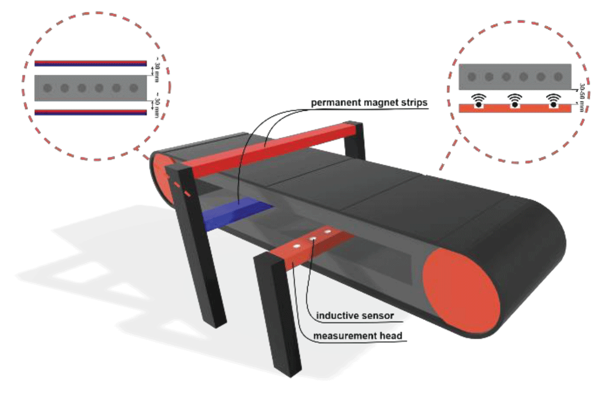
The DiagBelt+ diagnostic system, developed at the Wrocław University of Science and Technology, has been successfully implemented at the Bełchatów Lignite Mine in Poland [88Jurdziak L, Błażej R, Kirjanów-Błażej A, Rzeszowska A. Comparison of different metrics of belt condition used in lignite mines for taking decision about belt segments replacement and refurbishment, 2024, p. 501-18. https://doi.org/10.1007/978-3-031-44282-7_39.,99https://diagbeltplus.pwr.edu.pl/ 2024.]. This system utilizes the magnetic field stored in the steel cords of the core, thanks to their pre-magnetization. Inductive coils of the measurement head record changes in the magnetic field resulting from any discontinuity in the cord (damage or belt splice). The schematic of the DiagBelt+ diagnostic system is presented in Figure 2.
Figure 2: Schematic of the installation of the DiagBelt+ diagnostic system on a conveyor belt.
The DiagBelt+ measurement system consists of a measuring head (with magnetic coils), two permanent magnet strips (conditioning strips), a tachometer (encoder allowing for belt speed measurement), and a data acquisition module with a USB interface, which is responsible for data transmission between the measuring head and the computer.
The measuring head contains 90 coils distributed over a working length of 2250 mm. The measuring coils (measuring channels) are evenly spaced 25 mm apart. The measurement signals from the inductive coils are amplified and collected in the data acquisition module. The head is mounted at a specified distance from the examined belt, which is chosen based on the belt speed and the diameter of the steel cords in the belt core. The signal read by the measuring coils is thresholded and finally recorded as a matrix of discrete values: -1, 0, and +1. The measurement system software also enables data recording and export to a .csv file.
To ensure that a discontinuity or loss of the metallic cross-section of the steel cord can be detected by the inductive coils, the cords need to be magnetized beforehand. For this purpose, permanent magnet bars (conditioning bars) are installed above and below the examined conveyor belt, at equal distances (optimally 30 - 40 mm) from the belt covers. The process of magnetizing the steel cords requires several cycles of belt circulation (about 6-8).
The operating principle and capabilities of the diagnostic system have been extensively described in works [1010Jurdziak L, Błażej R, Kirjanów-Błażej A, Rzeszowska A. Trends in the Growth of Damage Extents in a Steel Conveyor Belt’s Core. Minerals. 2024 Feb; 14:174. https://doi.org/10.3390/min14020174.-1414Błażej R, Jurdziak L, Kirjanów-Błażej A, Bajda M, Olchówka D, Rzeszowska A. Profitability of conveyor belt refurbishment and diagnostics in the light of the circular economy and the full and effective use of resources. Energies (Basel). 2022 Oct; 15. https://doi.org/10.3390/en15207632.].
Geometry of belt splices
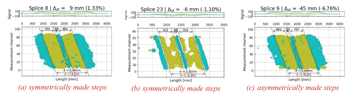
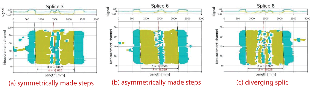
As a result of industrial research, diagnostic signals were collected from multiple belt loops, typically consisting of several segments (and thus splices) each. Figures 3-5 depict the recorded signals and the measured lengths and skewness coefficients in the case of a skewed splice. Belts with various parameters (loop length, number of sections, nominal strength, width, age at the time of testing, and transported material) were examined. The article presents belts operating under real conditions. In one figure (a, b, c), the signals of belt splices working on the same conveyor are shown.
Figure 3: Examples of signals from two-stage skewed belt splices along with the determined geometry.
Figure 4: Examples of signals from two-stage straight belt splices along with the determined geometry.
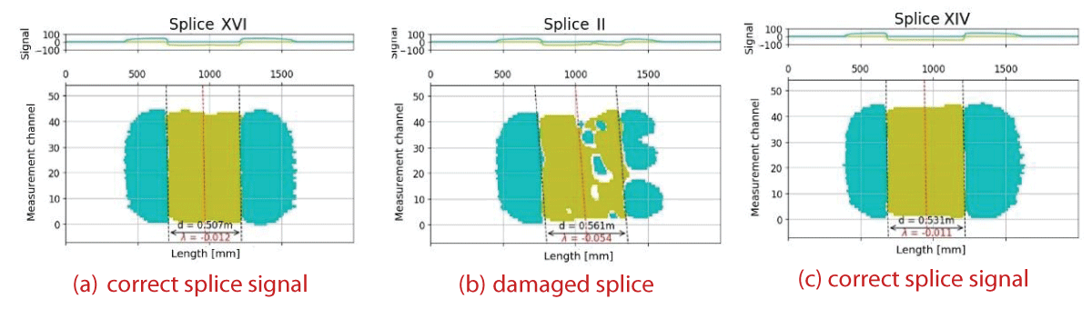
Figure 5: Examples of signals from single-stage straight belt splices along with the determined geometry.
Based on the signals from belt splices, not only the geometry of the splice is determined but also potential damage to the cords comprising the belt splice, which occurred during operation (an example of damage is shown in Figure 5b).
By analyzing the lengths of the signals obtained from the belt splices, it is possible to assess whether the connections were made correctly (maintaining the appropriate splice skewness coefficient λ), as well as whether the individual steps (in the case of 2-, 3-, and 4-step splices) have the same length. It often happens that the individual steps of the splice differ in length, and it is also encountered that the inter-cord offset is not symmetrical (Figure 3a).
The halt of transportation due to belt splice failure has significant economic consequences—not only from the necessity of re-executing the splice but also due to production losses caused by downtime. Therefore, the correctness of belt splice execution plays a crucial role, and assessing its geometry provides information about the correctness of its execution. It may happen that a splice is made with insufficient care, but after vulcanization, the user no longer has the ability to assess its geometry.
To evaluate the correctness of splice execution – its geometry – the DiagBelt+ diagnostic system can be utilized. Conducting a scan allows for determining the lengths of steps and the skewness coefficient, but it can also serve as a starting point for comparing signals from subsequent inspections and assessing the length of the splice during operation to prevent cord separation and resulting failures.
Therefore, diagnosing not only the segments themselves but also belt splices is justified. The DiagBelt+ diagnostic system developed at the Wrocław University of Science and Technology provides a wealth of information about how the belt is deteriorating, allowing inferences about conveyor malfunctions, eliminating them, and thereby influencing the belt’s lifespan.
Lodewijsk G. Applied belt splices design. Conference: SafeCon 1At: Johannesburg, South Africa, 2014.
Kozłowski T, Wodecki J, Zimroz R, Błazej R, Hardygóra M. A diagnostics of conveyor belt splices. Appl Sci (Switzerland). 2020; 10. https://doi.org/10.3390/APP10186259.
Temerzhanov A, Stolpovskikh I, Sładkowski A. Analysis of reliability parameters of conveyor belt joints. Transp Probl. 2012; 7.
Bugaric U, Tanasijevic M, Polovina D, Ignjatovic D, Jovancic P. Lost production costs of the overburden excavation system caused by rubber belt failure. Eksploatacja i Niezawodnosc. 2012; 14.
Webb C, Sikorska J, Khan RN, Hodkiewicz M. Developing and evaluating predictive conveyor belt wear models. Data-Centric Eng. 2020; 1. https://doi.org/10.1017/dce.2020.1.
Liu X, He D, Lodewijks G, Pang Y, Mei J. Integrated decision making for predictive maintenance of belt conveyor systems. Reliab Eng Syst Saf. 2019; 188. https://doi.org/10.1016/j.ress.2019.03.047.
Sikorska JZ, Hodkiewicz M, Ma L. Prognostic modelling options for remaining useful life estimation by industry. Mech Syst Signal Process. 2011; 25:1803-36. https://doi.org/10.1016/j.ymssp.2010.11.018.
Jurdziak L, Błażej R, Kirjanów-Błażej A, Rzeszowska A. Comparison of different metrics of belt condition used in lignite mines for taking decision about belt segments replacement and refurbishment, 2024, p. 501-18. https://doi.org/10.1007/978-3-031-44282-7_39.
https://diagbeltplus.pwr.edu.pl/ 2024.
Jurdziak L, Błażej R, Kirjanów-Błażej A, Rzeszowska A. Trends in the Growth of Damage Extents in a Steel Conveyor Belt’s Core. Minerals. 2024 Feb; 14:174. https://doi.org/10.3390/min14020174.
Jurdziak L, Błażej R, Kirjanów-Błażej A, Rzeszowska A. Transverse Profiles of Belt Core Damage in the Analysis of the Correct Loading and Operation of Conveyors. Minerals. 2023 Dec; 13:1520. https://doi.org/10.3390/min13121520.
Błażej R, Jurdziak L, Kirjanow-Blazej A, Kozlowski T. Identification of damage development in the core of steel cord belts with the diagnostic system. Sci Rep. 2021 Mar; 11. https://doi.org/10.1038/s41598-021-91538-z.
Rzeszowska A, Jurdziak L, Błażej R, Kirjanów-Błażej A. Application of Clustering and SOM Analysis for Identification of Conveyor Belt Damage Based on Data from the Diagbelt + Magnetic System, 2023, p. 461–75. https://doi.org/10.1007/978-3-031-45021-1_35.
Błażej R, Jurdziak L, Kirjanów-Błażej A, Bajda M, Olchówka D, Rzeszowska A. Profitability of conveyor belt refurbishment and diagnostics in the light of the circular economy and the full and effective use of resources. Energies (Basel). 2022 Oct; 15. https://doi.org/10.3390/en15207632.
Błażej R, Jurdziak L, Kirjanów-Błażej A, Kostrzewa P, Rzeszowska A. Dimensioning of Splices Using the Magnetic System. IgMin Res. Jun 25, 2024; 2(6): 469-472. IgMin ID: igmin204; DOI:10.61927/igmin204; Available at: igmin.link/p204
1Faculty of Geoengineering, Mining and Geology, Wroclaw University of Science and Technology, Na Grobli 15, 50-421 Wrocław, Poland
2Faculty of Information and Communication Technology, Wroclaw University of Science and Technology, Janiszewskiego 11/17, 50-372 Wrocław, Poland
3Bestgum Polska sp. z o.o., św. Barbary 3, 97-427 Rogowiec, Poland
Address Correspondence: Leszek Jurdziak, Faculty of Geoengineering, Mining and Geology, Wroclaw University of Science and Technology, Na Grobli 15, 50-421 Wrocław, Poland, Email: [email protected]
How to cite this article: Błażej R, Jurdziak L, Kirjanów-Błażej A, Kostrzewa P, Rzeszowska A. Dimensioning of Splices Using the Magnetic System. IgMin Res. Jun 25, 2024; 2(6): 469-472. IgMin ID: igmin204; DOI:10.61927/igmin204; Available at: igmin.link/p204
Figure 1: Schematic of connecting cords in a two-step splice...
Figure 2: Schematic of the installation of the DiagBelt+ dia...
Figure 3: Examples of signals from two-stage skewed belt spl...
Figure 4: Examples of signals from two-stage straight belt s...
Figure 5: Examples of signals from single-stage straight bel...
Lodewijsk G. Applied belt splices design. Conference: SafeCon 1At: Johannesburg, South Africa, 2014.
Kozłowski T, Wodecki J, Zimroz R, Błazej R, Hardygóra M. A diagnostics of conveyor belt splices. Appl Sci (Switzerland). 2020; 10. https://doi.org/10.3390/APP10186259.
Temerzhanov A, Stolpovskikh I, Sładkowski A. Analysis of reliability parameters of conveyor belt joints. Transp Probl. 2012; 7.
Bugaric U, Tanasijevic M, Polovina D, Ignjatovic D, Jovancic P. Lost production costs of the overburden excavation system caused by rubber belt failure. Eksploatacja i Niezawodnosc. 2012; 14.
Webb C, Sikorska J, Khan RN, Hodkiewicz M. Developing and evaluating predictive conveyor belt wear models. Data-Centric Eng. 2020; 1. https://doi.org/10.1017/dce.2020.1.
Liu X, He D, Lodewijks G, Pang Y, Mei J. Integrated decision making for predictive maintenance of belt conveyor systems. Reliab Eng Syst Saf. 2019; 188. https://doi.org/10.1016/j.ress.2019.03.047.
Sikorska JZ, Hodkiewicz M, Ma L. Prognostic modelling options for remaining useful life estimation by industry. Mech Syst Signal Process. 2011; 25:1803-36. https://doi.org/10.1016/j.ymssp.2010.11.018.
Jurdziak L, Błażej R, Kirjanów-Błażej A, Rzeszowska A. Comparison of different metrics of belt condition used in lignite mines for taking decision about belt segments replacement and refurbishment, 2024, p. 501-18. https://doi.org/10.1007/978-3-031-44282-7_39.
https://diagbeltplus.pwr.edu.pl/ 2024.
Jurdziak L, Błażej R, Kirjanów-Błażej A, Rzeszowska A. Trends in the Growth of Damage Extents in a Steel Conveyor Belt’s Core. Minerals. 2024 Feb; 14:174. https://doi.org/10.3390/min14020174.
Jurdziak L, Błażej R, Kirjanów-Błażej A, Rzeszowska A. Transverse Profiles of Belt Core Damage in the Analysis of the Correct Loading and Operation of Conveyors. Minerals. 2023 Dec; 13:1520. https://doi.org/10.3390/min13121520.
Błażej R, Jurdziak L, Kirjanow-Blazej A, Kozlowski T. Identification of damage development in the core of steel cord belts with the diagnostic system. Sci Rep. 2021 Mar; 11. https://doi.org/10.1038/s41598-021-91538-z.
Rzeszowska A, Jurdziak L, Błażej R, Kirjanów-Błażej A. Application of Clustering and SOM Analysis for Identification of Conveyor Belt Damage Based on Data from the Diagbelt + Magnetic System, 2023, p. 461–75. https://doi.org/10.1007/978-3-031-45021-1_35.
Błażej R, Jurdziak L, Kirjanów-Błażej A, Bajda M, Olchówka D, Rzeszowska A. Profitability of conveyor belt refurbishment and diagnostics in the light of the circular economy and the full and effective use of resources. Energies (Basel). 2022 Oct; 15. https://doi.org/10.3390/en15207632.


 スキャンしてリンクを取得