Welcome to IgMin Research – an Open Access journal uniting Biology, Medicine, and Engineering. We’re dedicated to advancing global knowledge and fostering collaboration across scientific fields.
Welcome to IgMin, a leading platform dedicated to enhancing knowledge dissemination and professional growth across multiple fields of science, technology, and the humanities. We believe in the power of open access, collaboration, and innovation. Our goal is to provide individuals and organizations with the tools they need to succeed in the global knowledge economy.
IgMin Publications Inc., Suite 102, West Hartford, CT - 06110, USA
The field of Unmanned Aerial Vehicles (UAVs) has witnessed a surge in demand for efficient and optimized designs, prompting researchers to explore advanced methodologies. This literature review delves into key aspects of integrating multi-granular fidelity optimization and innovative parameterization for UAV design, reviewing existing literature to provide a comprehensive background for the proposed research [1-60].
The evolving landscape of Unmanned Aerial Vehicle (UAV) design demands an integrated approach, harmonizing low-grained and high-grained fidelity methods. Notably, the utilization of low-grained fidelity tools facilitates swift aerodynamic exploration, generating an exponential number of samples, which could be difficult to individually analyze [1]. The subsequent transition to high-grained simulations, employing industry-standard tools such as ANSYS and Hyper Mesh, ensures proper validation and precise analysis of selected designs [1,61-63].
Resource optimization is intrinsic to this methodology, directing high-grained simulations towards a judiciously curated subset of designs identified as promising through low-grained exploration. The efficiency impact is substantial, as the integration of speed and precision expedites decision-making in preliminary and conceptual design phases [3,5,64-75]. This strategic two-tiered design process offers a systematic exploration of multidisciplinary aspects of UAV design, emphasizing the intricate interplay of aero-structural optimization.
Optimization of structures is utilized in most studies to obtain more efficiency in said design considering there are new discoveries made in the field of engineering and design. Methods like finite elements analysis, computational fluid dynamics, and materials optimization allow for an efficient restructuring, adjustment, and optimization of aircraft structures [7,12,14,16]. In alignment with the topic of research, the UAV to be analyzed is the LSU-02 NGLD, the drone was designed primarily to counter the fishing surveillance problem facing the Indonesian sea. LSU-02 NGLD has a longer cruising range of 350 km and a mission range of 100 km [4,13,15,17].
This UAV is designed to have a maximum mass of 21 kg for 5 hours of endurance at 300 m altitude [9,10,18]. The reconstruction of the wing formation will allow for a reduction in weight which could increase the efficiency and payload of the air-vehicle. The UAV wing consists of ribs made of balsa wood, spars made of aluminum, and skin made of composite material consisting of Balsa/Epoxy and E-glass wood [10,20,21,24]. An optimization and reconstruction of the initial material will allow for a lighter air vehicle in turn increase speed and reduce fuel consumption [3,19,25,28].
The experiment carried out on the LSU-02 NGLD showcases the need to be cautious of the mass addition on the wing. The Whiffletree Method shows the wing is only capable of withstanding an additional load of 2.4 kg before reaching its yield point [20,32,36,38]. Wing total weight is 2 kg – 3 kg and any addition has to be carefully monitored. Considering the increase in mass and less share stress using structures such as aluminium and glass fibre, an introduction of newer materials can increase the agility and share stress the wings could endure [4,7,44,45]. The fibre reinforced poly mar is the most efficient and lighter composite material which could be used in the structural design of UAV wings considering a high ratio of young modulus, tensile strength, and compressive strength [7,23,46-48,50].
Research significance
This research endeavors to contribute to the optimization process in Unmanned Aerial Vehicle (UAV) design by introducing a cost and computational time-efficient approach that combines fine and coarse granularity methods. The methodology addresses critical scientific challenges inherent in UAV design optimization, offering a promising solution to the complex interplay of aero-structural optimization. The essence of this research lies in its methodological thrust, aimed at innovating within the domain of Unmanned Aerial Vehicle (UAV) design. The project confronts significant scientific challenges, primarily the need to seamlessly integrate disparate methodologies to address the complexities inherent in UAV design optimization. The field of optimization always prioritizes the need for more efficient and time-reducing methods to obtain optimal design.
Potential impact
The adoption of a multi-granularity fidelity optimization approach holds significant promise for the aerospace industry. By harnessing the power of both fine and coarse granularity methods, this research aims to achieve unprecedented levels of efficiency and accuracy in UAV design optimization. The seamless integration of diverse disciplines and the utilization of advanced computational tools pave the way for groundbreaking advancements in air mobility.
Moreover, the feasibility of this research is bolstered by recent advancements in computational techniques, machine learning algorithms, and interdisciplinary collaboration. The integration of fine and coarse granularity methods presents a viable pathway toward overcoming existing limitations in UAV design optimization, offering a transformative solution to the complex challenges faced by the aerospace industry.
In conclusion, this research represents a significant step forward in the optimization of UAV design, offering a pioneering approach that promises to revolutionize the field. By combining fine and coarse granularity methods, this methodology opens new avenues for innovation and discovery, positioning the aerospace industry for a future of unprecedented efficiency and performance in UAV design optimization.
Key scientific problems
The optimization of UAV design poses significant challenges due to the intricate interaction of multiple disciplines and the need for simultaneous exploration and validation. Traditional approaches often struggle to reconcile the divergent demands of efficiency and accuracy within a computationally feasible framework. Moreover, the sheer volume of design parameters compounds the computational burden, necessitating a breakthrough methodology to navigate this complexity effectively.
Proposed solutions
Multi-Granularity Design and Optimization: Implementing an optimization strategy that embraces fine and coarse granularity methods, this approach allows for the alternating use of detailed and broader-scale analyses. By integrating fine-grained details with broader strokes, this method enhances efficiency and time savings while addressing the multifaceted challenges in aerospace applications, including aerodynamics, structures, and acoustics.
The approach could allow for a thorough exploration of multidisciplinary parameters such as composite material, orientation, spar and rib material, deformation, stress, strain, safety factor, noise, and weight allowing for alternation between high and low-fidelity optimization methods, ensuring a comprehensive understanding of the design space and identification of optimal UAV configurations. The method could help identify potential applications of the developed UAV design methodologies, including applications in transportation, surveillance, and services.
The methods showed great potential to assess the broader implications of the research on the UAV industry, considering advancements in efficiency, structural integrity, and noise reduction. The research objectives collectively aim to contribute to the advancement of UAV design by integrating innovative parameterization techniques and optimizing multidisciplinary aspects through a combination of coarse and fine-grain fidelity methods. The outcomes have the potential to influence various fields, from aerospace engineering to applications requiring efficient and optimized UAV technologies from equation (2.1), which illustrates the theoretical representation methodology. The generic governing equation for incorporating coarse and fine grain fidelity findings, represented as Gcg and Gfg respectively, is expressed as follows in equation (2.1).
(2.1)
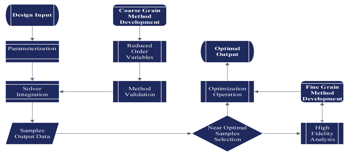
Gfg denotes the output of the high-fidelity simulation, typically performed using advanced computational tools, which provides detailed and accurate results. Gcg represents the output of the low-fidelity simulation, often conducted using simplified or approximate methods such as XFLR5, which offers faster and more cost-effective results. Summation of ki components accounts for the adjustments needed to align the coarse grain-fidelity findings with the high-fidelity results. It involves summing over n trend values ki multiplied by their respective changes ∆ki. For the ki represents the trend values reflection between the low and high-fidelity simulations for various parameters. A positive ki indicates that the high-fidelity simulation yields higher values compared to the low-fidelity simulation, while a negative -ki signifies the opposite. Fi changes are the differences in the parameters of interest between the low and high-fidelity simulations. This includes variations in aerodynamic coefficients, structural properties, or other relevant parameters depending on the specific application as illustrated in Figure 1.
Figure 1: Methodology Demonstration.
The UAV design landscape integrates coarse and fine-fidelity methods, leveraging swift exploration with low-fidelity tools followed by meticulous validation using high-fidelity simulations. This approach optimizes resources, expedites decision-making, and systematically explores multidisciplinary aspects of UAV design.
Trend validation
Upon successful validation, engineers scrutinize optimization results for trends and patterns indicative of optimal design configurations. Trend validation serves as a critical checkpoint, confirming the consistency and reliability of optimization outcomes before transitioning to higher-fidelity analyses.
Structural optimization approach
Structural Optimization with the anticipated method will involve the integration of reduce order optimization and method validation, after validation and it shows signs of trend validation, we’ll then proceed for high fidelity optimization with a few near optimal cases. A method that helps solve for structural solver will utilize easier methods of solving things with less accuracy, random optimization can be conducted whiles changing variables to get the optimal cases then those will be validated in a high-fidelity solver like FEM.
One key component of the Coarse Granularity Application is the incorporation of constitutive laminate theory, which provides a systematic framework for characterizing the mechanical behavior of composite materials used in the UAV’s construction. By manipulating laminate configurations, material properties, and layup angles, engineers can assess the impact of various design parameters on structural stiffness, strength, and durability.
Structural optimization represents a critical phase in the design and development of aerospace structures, necessitating a systematic approach to enhance performance, efficiency, and reliability. The optimization process entails a multifaceted strategy that integrates reduced-order optimization techniques with rigorous method validation, culminating in high-fidelity optimizations based on near-optimal solutions.
Reduced-order optimization
Leveraging reduced-order optimization methodologies, engineers embark on iterative optimization cycles aimed at refining structural designs and configurations. These techniques, though less computationally intensive, provide valuable insights into design trends and enable rapid exploration of design spaces. In conjunction with reduced-order optimization techniques, such as topology optimization or parametric modeling, advanced structural analysis methods are employed to evaluate the performance of UAV components under various loading conditions. Finite Element Analysis (FEA) simulations are utilized to assess the structural integrity, stiffness, and fatigue resistance of critical components.
Additionally, modal analysis is conducted to identify natural frequencies and vibration modes, ensuring that structural designs meet resonance avoidance criteria and operational safety requirements. The optimization process also considers manufacturing constraints, such as material availability and fabrication techniques, to ensure the feasibility and cost-effectiveness of the proposed designs.
Random optimization
Random optimization techniques, coupled with stochastic sampling methods, facilitate the exploration of vast design spaces and the identification of promising design configurations. By iteratively perturbing design variables within predefined bounds, engineers uncover optimal or near-optimal solutions with enhanced efficiency.
High-fidelity optimization
With the validated trends in hand, engineers proceed to high-fidelity optimization utilizing advanced computational tools such as Finite Element Analysis (FEA). High-fidelity optimization techniques offer increased accuracy and detail, enabling engineers to fine-tune designs and refine structural performance characteristics. Additionally, the structural optimization approach involves advanced material modeling techniques, such as composite laminate theory and micromechanical modeling, to accurately predict the behavior of composite materials under different loading conditions. By considering the anisotropic nature of composite materials and the effects of ply orientation on mechanical properties, engineers can optimize laminate configurations to maximize structural performance while minimizing weight. Furthermore, the optimization process incorporates probabilistic design methods to account for uncertainties in material properties and manufacturing processes, ensuring that optimized designs maintain structural integrity and reliability throughout their operational lifespan.
Sensitivity analysis
Throughout the optimization process, sensitivity analysis plays a pivotal role in identifying influential design parameters and their impact on structural performance. By systematically varying input parameters and assessing their effects on optimization outcomes, engineers gain valuable insights into design sensitivities and trade-offs.
Structural method application
The structural application section presents a comprehensive examination of the LSU-02 NGLD UAV’s structural integrity and performance characteristics, paving the way for detailed analysis and optimization strategies. Divided into Coarse Granularity Application and Fine Granularity Application, this section delves into two distinct yet interconnected approaches to structural optimization as illustrated in Figure 2.
One key component of the Coarse Granularity Application is the incorporation of constitutive laminate theory, which provides a systematic framework for characterizing the mechanical behavior of composite materials used in the UAV’s construction. By manipulating laminate configurations, material properties, and layup angles, engineers can assess the impact of various design parameters on structural stiffness, strength, and durability.
Moreover, the Coarse Granularity Application serves as a platform for exploring trade-offs between design objectives such as weight reduction, stiffness enhancement, and manufacturing feasibility. By iteratively refining the structural design based on insights gained from coarse fidelity analyses, engineers can identify promising design alternatives that strike a balance between competing requirements and constraints. The Coarse Granularity Application plays a vital role in the structural optimization process, laying the groundwork for more advanced analyses and refinement in subsequent stages. Through its emphasis on simplicity, efficiency, and exploratory analysis, the section could light a valuable insight into the UAV’s structural behavior and make informed decisions that drive the optimization process forward.
Transitioning to the Fine Granularity Application, we delve deeper into refining and validating the structural optimization process. Here, meticulous attention is paid to intricate details, ensuring accuracy and reliability in the analysis. By fine-tuning parameters and optimizing the structural design, we aim to enhance the UAV’s performance while maintaining structural integrity and safety standards.
Through computational simulations, empirical testing, and theoretical analysis, this section endeavors to unravel the complex interplay between design, materials, and structural performance. By elucidating key factors such as load-bearing capacity, stress distribution, and deformation characteristics, we seek to provide valuable insights into optimizing the UAV’s structural design for enhanced efficiency and reliability in various operational scenarios all showcased in Figure 2.
Moving forward, flutter analysis takes center stage as we delve into the intricate dynamics of aeroelastic phenomena. This critical analysis assesses the UAV’s susceptibility to flutter, a potentially destabilizing oscillation caused by the interaction of aerodynamic forces and structural dynamics. By simulating various flight scenarios and analyzing the UAV’s response to aerodynamic loads, we identify critical flutter speeds, mode shapes, and damping characteristics to mitigate the risk of structural instability and ensure safe flight operations.
Finally, buckling analysis provides invaluable insights into the UAV’s structural stability and load-bearing capacity under compressive forces. Through computational modeling and theoretical analysis, we examine the UAV’s resistance to buckling-induced failure, considering factors such as material properties, geometric imperfections, and boundary conditions. By identifying critical buckling modes, load thresholds, and failure mechanisms, we optimize the structural design to enhance overall safety, reliability, and performance in demanding aerospace environments.
Fine Granularity Application represents a holistic approach to structural optimization, encompassing static, dynamic, and stability analyses to ensure the LSU-02 NGLD UAV’s structural integrity and performance excellence across a wide range of operational scenarios. Through meticulous attention to detail and rigorous analysis techniques, we aim to push the boundaries of aerospace engineering, delivering innovative solutions that set new standards for efficiency, safety, and reliability in unmanned aerial vehicle design.
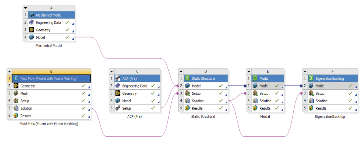
The undertaken analysis leveraged the capabilities of ANSYS and, the integration of various modules to provide a comprehensive understanding of the composite wing’s behavior. This multidisciplinary approach involved the integration of aerodynamics analysis from Fluent, structural analysis from Static Structural, and composite material analysis through the ANSYS Composite Pre/Post (ACP) module.
Coarse granularity application
Coarse Granularity Application serves as a platform for exploring trade-offs between design objectives such as weight reduction, stiffness enhancement, and manufacturing feasibility. By iteratively refining the structural design based on insights gained from coarse fidelity analyses, engineers can identify promising design alternatives that strike a balance between competing requirements and constraints.
In the Fine Granularity Application, our focus extends beyond basic structural optimization to encompass a multifaceted analysis of the LSU-02 NGLD UAV’s structural performance under varying conditions. This advanced phase of analysis comprises three pivotal aspects: static structural analysis, flutter analysis, and buckling.
Overall, the Coarse Granularity Application plays a vital role in the structural optimization process, laying the groundwork for more advanced analyses and refinement in subsequent stages. Through its emphasis on simplicity, efficiency, and exploratory analysis, this phase empowers engineers to gain valuable insights into the UAV’s structural behavior and make informed decisions that drive the optimization process forward.
In the Coarse Granularity Application, our focus extends beyond basic structural optimization to encompass a multifaceted analysis of the LSU-02 NGLD UAV’s structural performance under varying conditions. This advanced phase of analysis comprises three pivotal aspects: static structural analysis, flutter analysis, and buckling analysis.
Skin optimization modeling
In the Coarse Granularity Application, the focus lies on employing constitutional laminate theory manipulation to understand and optimize the structural behavior of the UAV. By integrating various parameters such as material properties, laminate configuration angles (0°, 45°, 90°), area, and thickness into the equation, we aim to derive insightful data regarding the UAV’s structural response. The skin, comprising six layers, forms the basis for computational samples, enabling the extraction of comprehensive values for each coordinate and facilitating a holistic understanding of the structural dynamics. This stiffness matrix represents the composite material’s behavior in the z-direction and is essential for analyzing its mechanical properties. Calculate the stiffness matrix for each layer and apply the appropriate transformation matrices. The overall stiffness matrix for the laminate. In the ever-evolving landscape of aerospace engineering, where the seamless integration of aerodynamics and structural robustness is non-negotiable, the careful selection and orchestration of composite materials stand as a linchpin.
This essay embarks on a journey through the intricate methodology employed to evaluate and optimize laminate composites, casting a spotlight on three distinctive materials: Epoxy E-Glass, Epoxy S-Glass, and Epoxy Carbon Fiber Unidirectional (UD). The overarching goal is to ascertain the most suitable material for a wing application, taking into account both the calculated stiffness along the z direction and the inherent strength of the composite. Before delving into the intricacies of optimization, let’s take a moment to reacquaint ourselves with the fundamental properties of each material. Epoxy E-Glass boasts a Young’s Modulus E Aof 72 GPa and a Poisson’s Ratio (v) of 0.2. Yet, beckon, anticipating the filling of values following a thorough analysis. The governing computational equation is represented, see equation (3.1).
(3.1)
The overall stiffness matrix S is obtained by summing the contributions from each ply Calculation of Ti × Qi × ti for each ply for each ply, multiply the stiffness matrix Qi by the ply thickness ti before applying the transformation matrix Transpose Ti and multiply the result by Ti × Qi × ti calculated in Step 1. Sum the contributions from all plies to obtain the overall stiffness matrix s.
Let’s perform these calculations with material thickness incorporated. We’ll continue with the ply angles [90, 0, 45, 0, 45, 0] and assume a uniform unit thickness for all plies. To integrate material thickness into the calculation, we’ll adjust the process as follows which is the multiplication of all sequences of the stuffiness matrix. Calculation of Ti × Qi × ti for Each Ply for each ply, we multiply the stiffness matrix Qi by the ply thickness ti before applying the transformation matrix Ti to calculate the stiffness in the z-direction, you need to extract the (3,3) element from the resulting [STotal] matrix. This element represents the stiffness in the z-direction. substituting the values of material properties, ply orientations, and thicknesses into these equations, you can calculate the overall stiffness matrix for the composite material. Make sure to use consistent units (Pascals, meters, etc.) for accurate calculations.
Now, to solve for the stiffness matrix. Determine the material properties, including Young’s Modulus and Poisson’s Ratio for each material (E-Glass and Polyester). Define the ply orientations in degrees, Specify the ply thicknesses for each layer. Calculate the stiffness matrix for each individual layer using the material properties. Calculate the transformation matrices for each ply orientation.
Stiffness along the Z-direction
The methodology employed entails the meticulous compilation of six layers, each characterized by unique orientations that collectively influence the overall stiffness along the Z direction. The transformation matrices depend on the specific orientation of each layer. Given the layer orientations 700 we can calculate the transformation matrices. The equation allows for the integration of various material properties and laminate configurations across multiple layers or sections to obtain the comprehensive overall stiffness matrix for the entire composite structure as illustrated in equation (3.2).
(3.2)
Where Qoverall is the overall stiffness matrix for the composite structure. N is the number of laminate layers or sections. Wi is the weighting factor for the ith layer or section, representing its contribution to the overall stiffness. Qi is the stiffness matrix for the ith layer or section. Each Qi stiffness matrix accounts for the material properties and laminate configuration of the corresponding layer or section. The weighting factors Wi are determined based on factors such as the area or volume of each layer or section within the composite structure as shown in equation (3.3) and equation (3.4).
(3.3)
(3.4)
The stiffness equation can be utilized to estimate for stiffness of outer and inner wings while considering the geometric shape parameters and material properties The overall stiffness matrix can be calculated using the constitutional laminate method.
The method can be used to solve for each of the laminates of a composite material and know the overall strength and stiffness. For cases with two or more laminate orientations, we could estimate the overall stiffness quicker using the proposed method as low fidelity which then allows us to select trend values and near-optimal solutions. For our case, the variables alternate between 6 layers with angles 0, 45, and 90 as the fixed variables. All possible matches are reduced and then the stiffness values for each case pairing can be obtained which then will be transferred to high-fidelity ACP for further authentication. For Layer 1 (0 degrees):
(3.5)
For Layer 2 (45 degrees):
(3.6)
For Layer 3 (90 degrees):
(3.7)
Now, we can calculate the overall stiffness matrix:
(3.8)
These values would include Q11, Q12, Q16, Q22, Q26, and Q66 for both sections. The components of [Q] can be calculated using the elastic constants of the material and the fiber orientation. For example, for the 0° layer (E-Glass Fiber), you can use the following equations.
(3.9)
Where Efis the Young’s Modulus of the fiber, Em is the Young’s Modulus of the matrix, νf is the Poisson’s Ratio of the fiber, and Gf is the shear modulus of the fiber.
The strategic selection of this orientation hinges on a nuanced understanding that, often, a reduction in stiffness correlates with heightened strength and a diminished susceptibility to fracture. The computational finding for the optimal case is shown in Table 1.
Table 1: Parameters using the Stiffness Matrix for Different Orientations.
Material
Epoxy E glass
Epoxy Carbon Fiber
Orientation (6 layers)
[90 0 90 0 90 0]
[0 45 90 0 0 90]
Stiffness Value
1.8864
1.7765
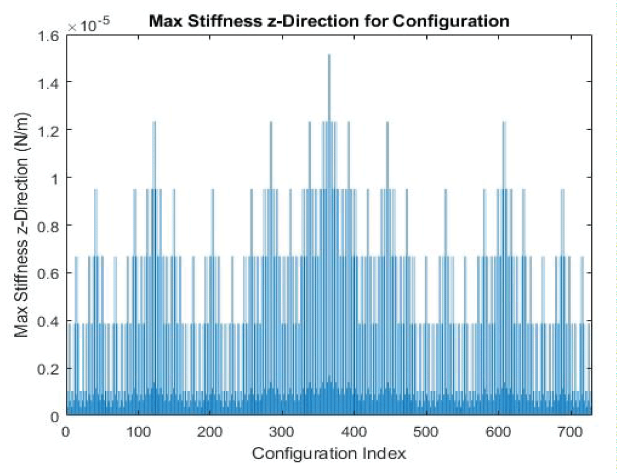
Our analysis of Epoxy E-Glass unfurls a tapestry of insights. The effective Young’s Modulus (Eeff) stands at approximately 69 GPa, dancing in tandem with a Poisson’s Ratio (Veff) of 0.28. These values, gleaned from the chosen orientation [0 45 90 0 0 90], not only illuminate the material’s behavior but also lay a foundation for grasping its role within the composite structure. The comprehensive table for Epoxy E-Glass, a testament to its potential, finds a home in the appendix. The graph showcases all possible cases of 6 layers in Figure 3.
Figure 3: Computational Stiffness Value for 6-Layer Configuration.
Using the transformation matrices and the stiffness matrices for individual layers to calculate the overall stiffness matrix for the laminate. Extract the (3,3) element of the resulting matrix to obtain Szz. The representation showcases each combination of various laminate configurations and the corresponding result we obtain from various combinations. The total number of combinations exceeds 700 cases which gives us a variety of cases to select depending on our requirements.
Calculation of Stiffness in the z-direction (Szz):
The goal is to evaluate and optimize composite materials, focusing on stiffness along the Z direction and inherent strength.
The methodology employed entails the meticulous compilation of six layers, each characterized by unique orientations that collectively influence the overall stiffness along the Z direction. The chosen orientation for analysis, [90 0 90 0 90 0], adds a layer of intrigue with its intentionally lower stiffness value (1.7765). The strategic selection of this orientation hinges on a nuanced understanding that, often, a reduction in stiffness correlates with heightened strength and a diminished susceptibility to fracture.
The strategic selection of this orientation hinges on a nuanced understanding that, often, a reduction in stiffness correlates with heightened strength and a diminished susceptibility to fracture. The computational finding for the optimal case is shown below in Table 2.
Table 2: Parameters using the Stiffness Matrix for Different Orientations.
Material
Epoxy E glass
Epoxy Carbon Fiber
Orientation (6 layers)
[90 0 90 0 90 0]
[0 45 90 0 0 90]
Stiffness Value
1.8864
1.7765
Our analysis of Epoxy E-Glass unfurls a tapestry of insights. The effective Young’s Modulus (Eeff) stands at approximately 69 GPa, dancing in tandem with a Poisson’s Ratio (Veff) of 0.28. These values, gleaned from the chosen orientation [0 45 90 0 0 90], not only illuminate the material’s behavior but also lay a foundation for grasping its role within the composite structure. The comprehensive table for Epoxy E-Glass, a testament to its potential, finds a home in the appendix. The graph showcases all possible cases of 6 layers in Figure 3. Using the transformation matrices and the stiffness matrices for individual layers to calculate the overall stiffness matrix for the laminate. Extract the (3,3) element of the resulting matrix to obtain Qoverall.
Fine granularity application
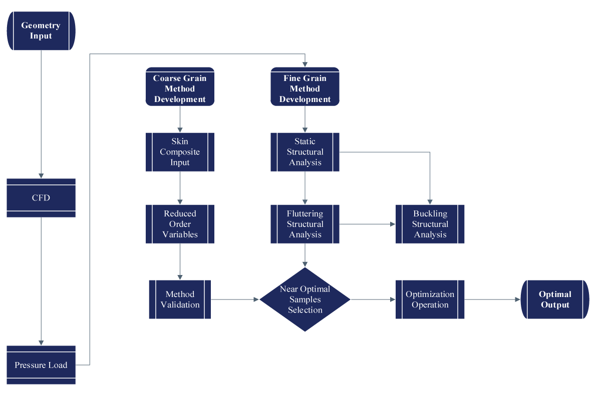
Static structural analysis forms the cornerstone of our investigation, aiming to understand how the UAV’s structure responds to static loads and stresses. Through rigorous computational simulations and empirical testing, we scrutinize the distribution of forces, deformation patterns, and stress concentrations within the UAV’s components. By assessing factors such as material properties, geometric configurations, and load-bearing capacities, we strive to optimize the structural design for maximum strength, stability, fluttering, and buckling in real-world operating conditions. The workflow is illustrated in Figure 4. The flow chart illustrates the comprehensive Aero-Structural Analysis methodology. A sample analysis mirrored the utilization of ANSYS Composite Pre/Post, showcasing a multidimensional workflow. This approach exemplifies the synergy achievable through ANSYS tools for a comprehensive understanding of composite wing performance.
Figure 4: Flow Chart for Aero-Structural Analysis.
Meshing and coupling
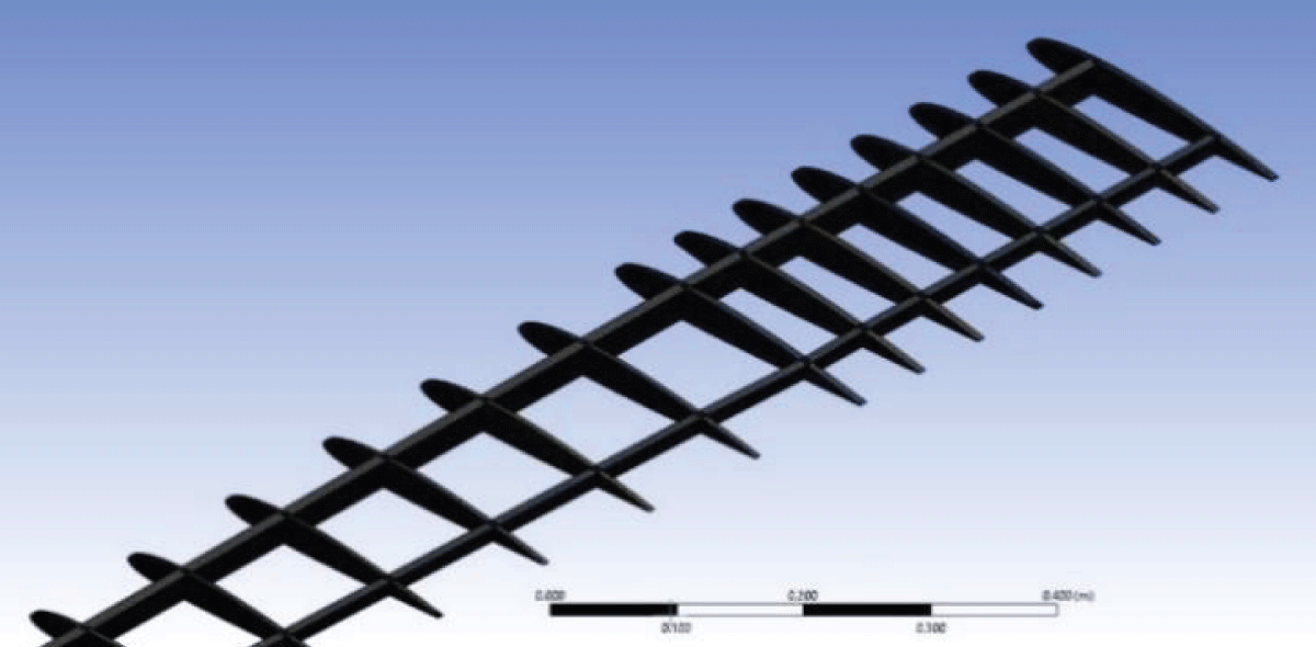
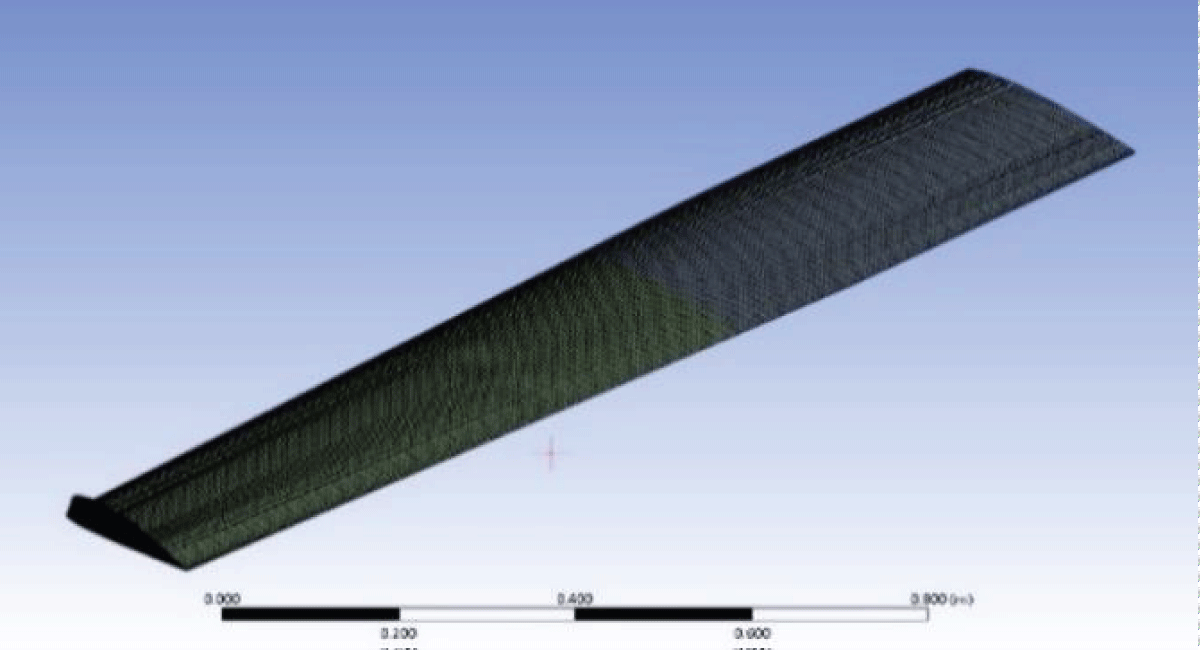
A meshing strategy using ACP for the wing skin and Ansys mechanical model for rib and spar components enhanced precision. Separate meshing of components allowed detailed analysis before integration, ensuring a holistic examination of structural performance. The ANSYS analysis employed a multidisciplinary approach, integrating Fluent for aerodynamics, Static Structural for structural analysis, and ANSYS Composite Pre/Post (ACP) for composite material analysis. The meshing and coupling are illustrated in Figures 5,6 for the rib, spar, and skin.
Figure 5: Rib and Spar Meshing on Mechanical Design.
Figure 6: Skin Coupled Meshing for Skin, Rib, and Spar.
The integration phase, involving coupling independently meshed components, maintained structural continuity. A manual connection technique ensured the accurate transmission of forces and deformations during the analysis.
This meshing and integration methodology balances precision and computational efficiency, providing insights into individual component behavior while ensuring overall wing assembly integrity.
CFD pressure load transfer
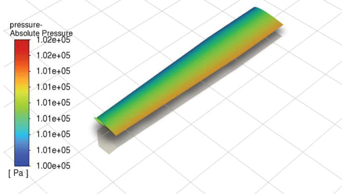
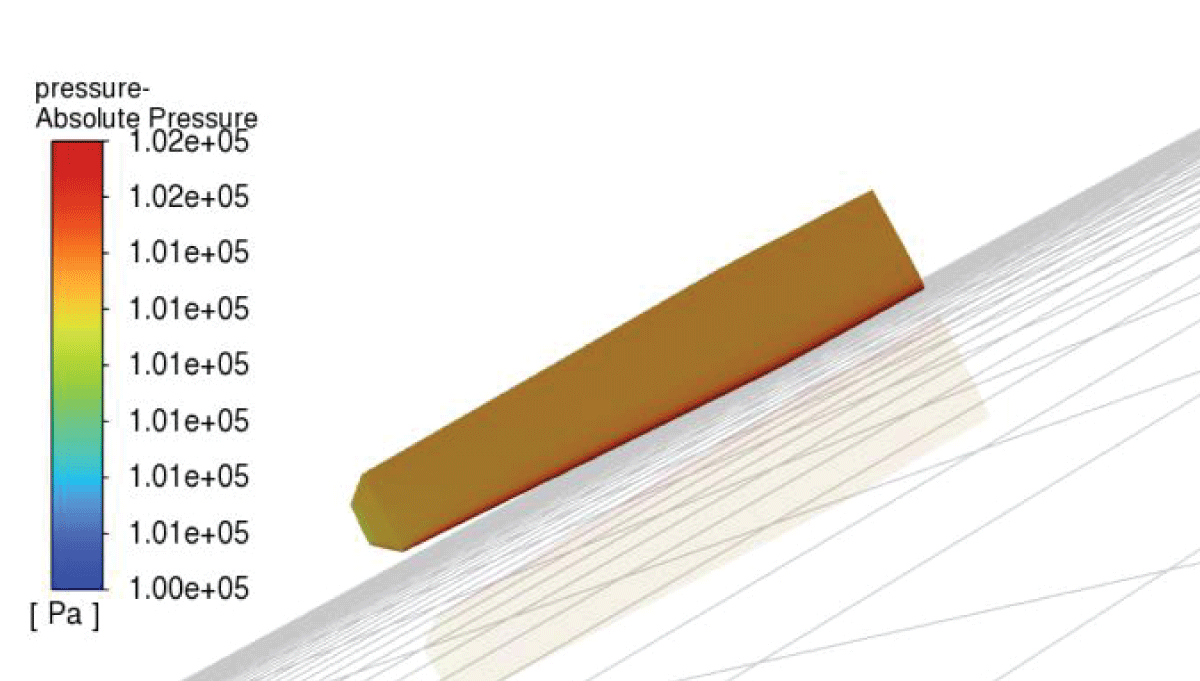
Fluent laid the foundation, conducting aerodynamics analysis to determine pressure loads crucial for understanding external forces on the wing. Fluent results provided inputs for subsequent structural analyses. Figures 7,8 illustrate the pressure for the lower and upper wing configuration of the optimized wing.
ACP composite material analysis
Figure 7: Pressure load distribution along the wing's lower surface.
Figure 8: Pressure load distribution along the wing upper surface.
The ACP module played a pivotal role in capturing composite material intricacies, allowing finite element modeling and material analysis. It facilitated seamless data transmission, enabling a holistic understanding of the composite structure.
Base model analysis
The comprehensive analysis of the base model, the Composite Base Wing, serves as a cornerstone in understanding the structural intricacies and performance metrics of a fundamental wing configuration. The base model features Al7075 as the primary material, providing a robust structural foundation. The parameters evaluated include deformation, stress, strain, factor of safety, and weight, collectively shedding light on the structural integrity and overall performance of the wing, an aerodynamics optimization was conducted, and a winglet was added in order to reduce vortexes impact on the wing (Table 3).
Table 3: Structural Specification Base Wing.
Epoxy Eglass
Al 7075
Deformation(mm)
7.5984
Stress
20.562
Strain
4.15E-04
Factor of safety
1.754
Weight (kg)
3.7525
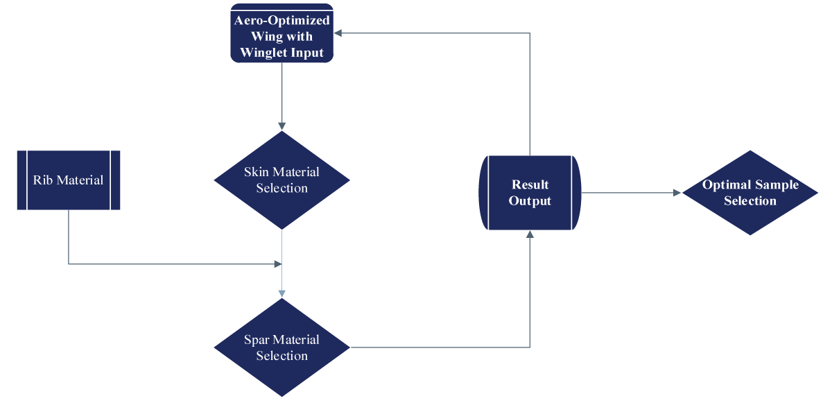
Optimization operations
The comprehensive analysis of the base model serves as a cornerstone in understanding the structural intricacies and performance metrics of a fundamental wing configuration. The base model features Al7075 as the primary material, Al7075, or Aluminum 7075, is a high-strength aluminum alloy known for its exceptional mechanical properties, making it widely used in various aerospace, automotive, and structural applications. is illustrated in Figure 9.
Figure 9: Structural Analysis and Optimization 1 Flowchart.
First optimization operation: The section will discuss the overall structural analysis and optimization operation for the UAV wing, it entitles the change of various materials to test for the spar and skin to obtain an optimal or near-optimal coupling. The methodological optimization process. The results findings are listed in Table 4 and shown in Figures 10,11.
Table 4: Analysis Parameters for Optimized Shape Epoxy E glass.
Material
Al 2024
Al 6061
Al 7075
Deformation
1.9946
2.0089
1.9946
Stress
20.562
20.504
20.563
Strain
4.15E-04
4.18E-04
4.15E-04
Factor of safety
1.754
1.75
1.761
Weight (kg)
3.7525
3.7171
3.773
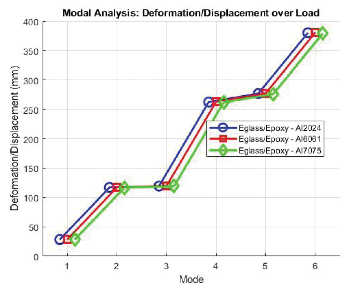
Figure 10: Fluttering Modes EGlass/Epoxy.
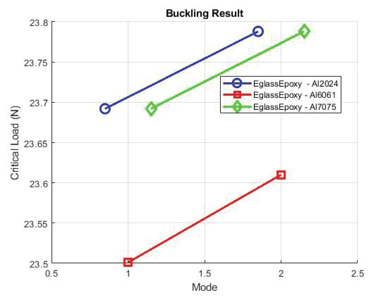
Figure 11: Buckling EGlass/Epoxy.
Case 1: Eglass/Epoxy - Al 2024 Composite Configuration
Deformation values show a maximum deformation of 1.9946 and an average of 0.77156 indicating the structural response of the wing with Al2024 as the spar material the Stress showcases a maximum strain of 20.562 and an average of 0.99015, the material experiences significant deformation under applied loads. The Strain value showcases the maximum stress of 4.15E-04 and an average of 2.38E-05 reflects the material’s ability to withstand external pressures.
Case 2: Spar Material - Al 6061 Composite Configuration
Deformation showcases the average deformation of 2.0089 and a maximum of 0.77775 suggesting a slightly higher structural response compared to Case 1. Strain values showcase a strain ranging from 4.18E-04 to 2.39E-05, Al6061 experiences deformation characteristics similar to Al2024. The stress of Al6061 exhibits stress levels comparable to Al2024, with average and maximum values indicating its ability to withstand external pressures effectively.
Case 3: Spar Material - Al 7075 Composite Configuration
The deformation values for Al7075 are similar to those of Al2024 and Al6061, with average and maximum values reflecting its structural response under applied loads. The strain of Al7075 exhibits strain characteristics comparable to Al2024 and Al6061, indicating similar deformation behavior. Stress levels of Al7075 align with those of Al2024 and Al6061, showcasing its capacity to withstand external pressures effectively.
Case 4: Epoxy S Glass with Al2024 Composite Configuration
Deformation shows a maximum deformation of 3.7524 and an average of 1.476 suggesting a significant structural response of the wing with Al2024 as the spar material in conjunction with Epoxy S Glass. Strain values with a maximum strain of 8.50E-04 and an average of 4.02E-05, the material experiences notable deformation under applied loads, indicating its flexibility. Stress showcases the maximum stress of 16.822 MPa and an average of 0.91901 MPa reflecting the material’s ability to withstand external pressures effectively. Visual illustrations are shown in Figures 12,13.
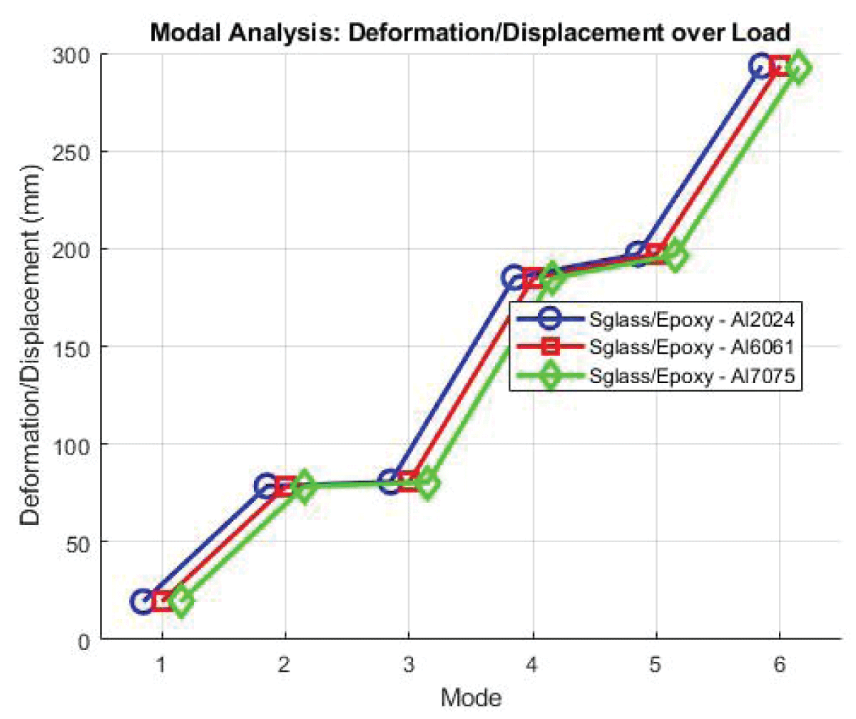
Figure 12: Fluttering SGlass/Epoxy.
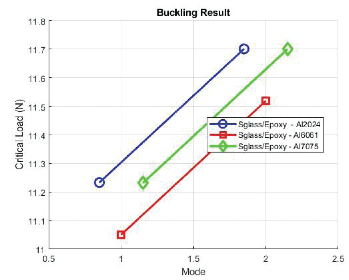
Figure 13: Buckling SGlass/Epoxy.
Case 5: Epoxy S Glass with Al6061 Composite Configuration
Deformation: The maximum deformation of 3.7914 and an average of 1.4936 suggest a slightly higher structural response compared to Case 4. Strain values with a strain ranging from 8.59E-04 to 4.07E-05, Al6061 in combination with Epoxy S Glass experience deformation characteristics similar to Al2024. The stress of Al6061 exhibits stress levels comparable to Al2024, with average and maximum values indicating its ability to withstand external pressures.
Case 6: Epoxy S Glass with Al7075 Composite Configuration
Deformation values showcase that the deformation values for Al7075 are similar to those of Al2024 and Al6061, with average and maximum values reflecting its structural response under applied loads. The strain of Al7075 exhibits strain characteristics comparable to Al2024 and Al6061, indicating similar deformation behavior. Stress shows the stress levels of Al7075 align with those of Al2024 and Al6061, showcasing its capacity to withstand external pressures effectively shown in Table 5.
Table 5: Analysis Parameters for Optimized Shape Epoxy S-Glass.
Composite
Epoxy S Glass
Material
Al 2024
Al 6061
Al 7075
Deformation
1.9946
2.0089
1.9946
Stress
16.822
16.465
16.799
Strain
8.50E-04
8.59E-04
8.50E-05
Factor of safety
1.754
1.75
1.761
Weight (kg)
3.7525
3.7171
3.773
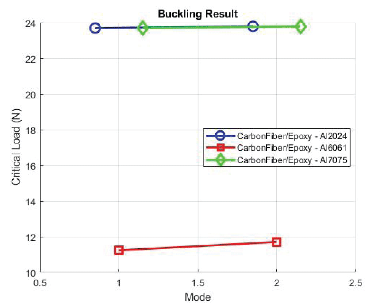
Case 7: Spar Material - Al2024 Composite Configuration
Deformation values show maximum deformation of 3.7524 and an average of 1.476 indicating the structural response of the wing with Al2024 as the spar material. Strain values with a maximum strain of 8.50E-04 and an average of 4.02E-05, the material experiences significant deformation under applied loads. Stress values with a maximum stress of 16.822 and an average of 0.91901 reflect the material’s ability to withstand external pressures. All visualization is shown in Figures 14,15.
Figure 14: Fluttering Modes Carbon Fibre/Epoxy.
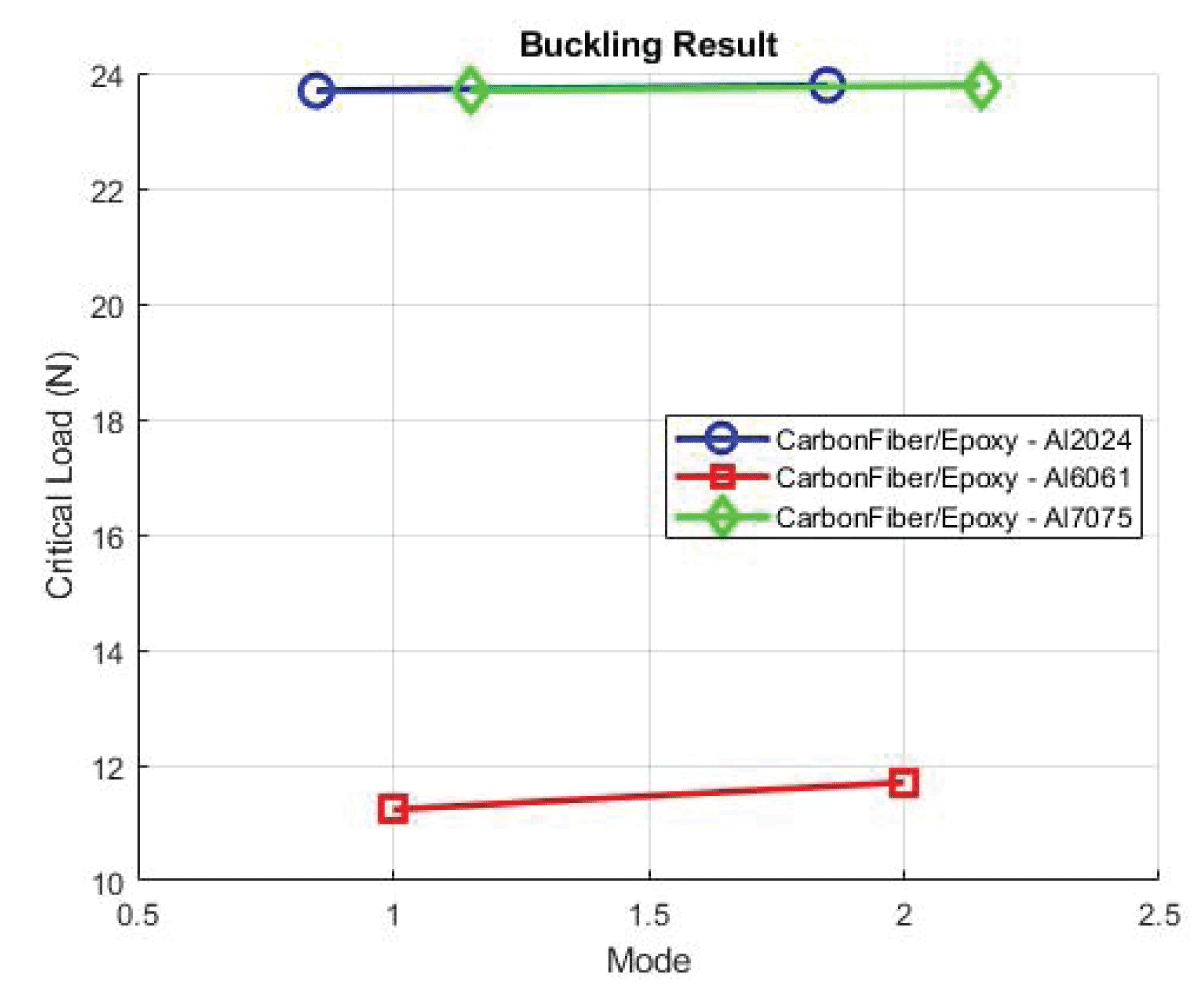
Figure 15: Buckling Epoxy Carbon Fibre.
Case 8: Spar Material - Al6061 Composite Configuration
Deformation values with a maximum deformation of 3.7914 and an average of 1.4936 suggest a slightly higher structural response compared to Case 7. Strain values showcases with a strain ranging from 8.59E-04 to 4.07E-05. Al6061 experiences deformation characteristics similar to Al2024. The stress of Al6061 exhibits stress levels comparable to Al2024, with average and maximum values indicating its ability to withstand external pressures.
Case 9: Spar Material - Al7075 Composite Configuration
Deformation shows the deformation values for Al7075 are similar to those of Al2024 and Al6061, with average and maximum values reflecting its structural response under applied loads. Strain Al7075 exhibits strain characteristics comparable to Al2024 and Al6061, indicating similar deformation behavior. Stress showcases the stress levels of Al7075 align with those of Al2024 and Al6061, showcasing its capacity to withstand external pressures effectively. The comparison highlights subtle differences in deformation, strain, and stress between the three cases, with variations likely attributed to material properties and composite configurations. Further analysis may focus on optimizing material selection to enhance structural performance while maintaining safety margins as shown in Table 6.
Table 6: Analysis Parameters for Optimized Shape.
Composite
Carbon Fibre
Epoxy
Epo
Material
Al 2024
Al 6061
Al 7075
Deformation (mm)
1.9636
3.7524
1.9946
Stress (N/m2)
20.562
16.804
20.563
Strain
4.15E-04
8.50E-04
4.15E-04
Factor of safety
1.754
1.75
1.761
Weight (kg)
3.7525
3.7171
3.773
Selection of optimized case
In this comprehensive simulation conducted using ANSYS, a total of nine samples were analyzed, systematically varying the materials for the wing skin, spar, and rib to explore their impact on structural performance. The wing skin was tested with three different composite materials: Epoxy E Glass, Epoxy S Glass, and Epoxy Carbon. For the spar, Aluminum alloys Al 2024, Al 6061, and Al 7075 were considered, while the rib utilized Balsa Wood consistently.
The simulation focused on key parameters such as stress, deformation, strain, factor of safety, and overall weight for each material combination. Notably, the results indicate variations in stress and deformation among the different materials, emphasizing the importance of material selection in optimizing the structural performance of UAV wings all illustrated in Table 7.
Table 7: Analysis Parameters for Optimized Shape.
Composite
Carbon Fibre
Material
Al 2024
Stress (N/m2)
1.9636
Deformation (mm)
20.562
Strain
4.15E-04
Factor of safety
1.754
Weight (kg)
3.5299
Epoxy Carbon Fiber Coupled with Al 2024 and Balsa Woodis the quest for an optimized wing configuration, the meticulous exploration of various material couplings and structural compositions plays a pivotal role. Among the considered cases, Case 7 featuring Epoxy Carbon Fiber as the skin material, Al 2024 as the spar material, and low-density balsa wood for the rib, emerges as the preferred choice. The selection is rooted in a careful balance of weight reduction, safety factors, and structural performance, particularly when compared to the base case without a winglet. The comprehensive nature of this simulation provides valuable insights into the intricate interplay of materials and their effects on the structural integrity and weight characteristics of the wing. This systematic exploration aims to inform and guide future decisions in UAV wing design and optimization, offering a nuanced understanding of the trade-offs associated with different material choices shown in Figures 16-18.
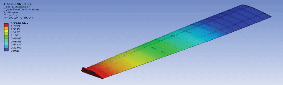
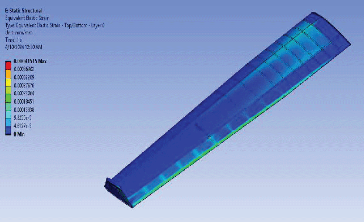
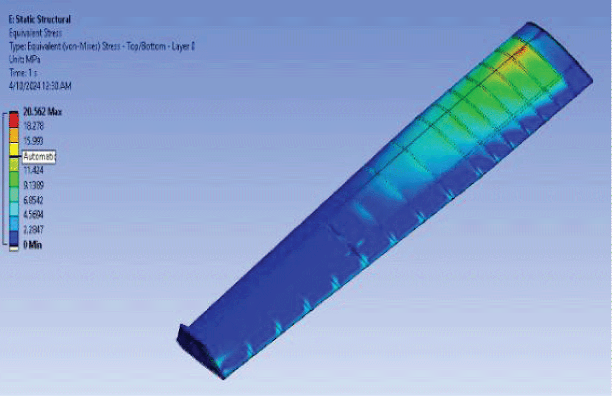
Figure 16: Deformation Static Optimized Wing 1.
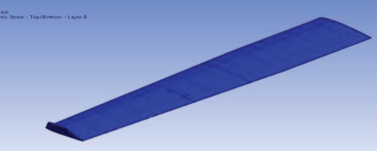
Figure 17: Strain Static Optimized Wing 1.
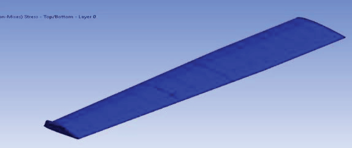
Figure 18: Stress Static Optimized Wing 1.
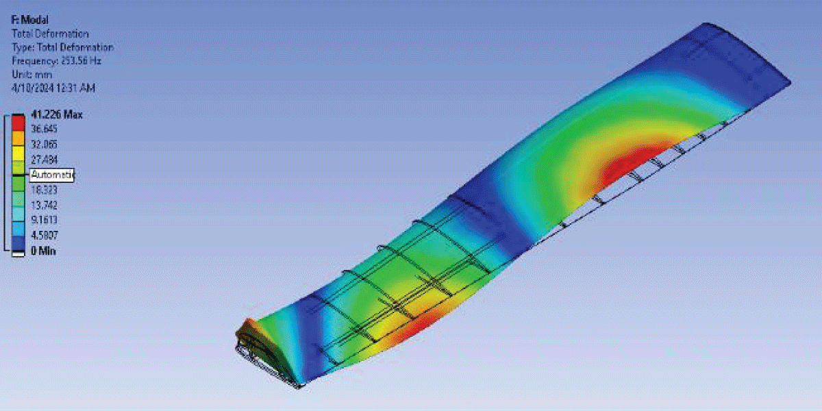
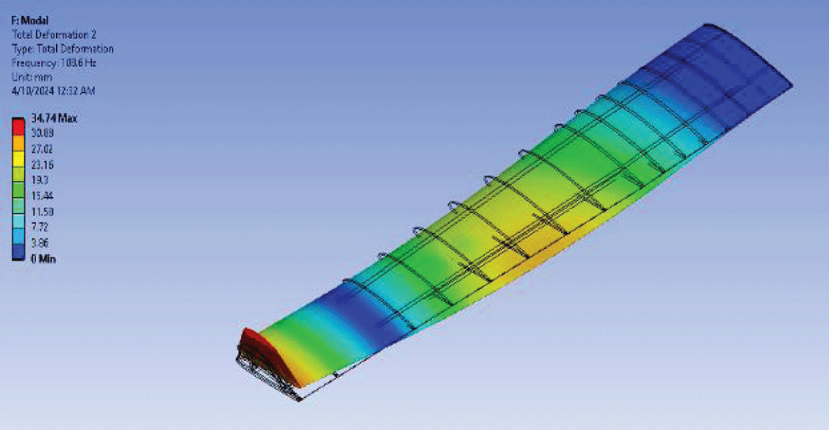
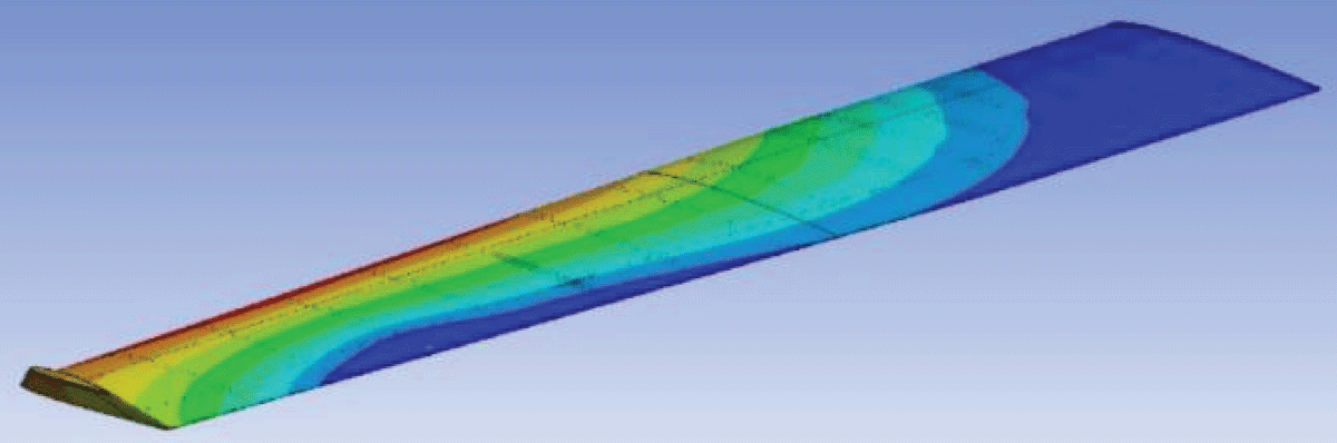
Expanding on the analysis, it’s noteworthy that the deformation, stress, and strain representations provide a comprehensive understanding of the structural behavior under static loading conditions. Notably, the combination of Epoxy Carbon Fiber and Al2024 exhibits pronounced deformation and stress levels, indicating areas for potential structural optimization. Figures 19-21 visually depict the deformation, stress, and strain distributions, respectively, offering valuable insights for further refinement.
Figure 19: Fluttering Mode 1.
Figure 20: Fluttering Mode 2.
Figure 21: Fluttering Mode 3.
Fluttering analysis
The flutter analysis and optimization of wing materials constitute a pivotal domain within aerospace engineering, exerting a profound impact on the structural integrity, aerodynamic performance, and overall stability of aircraft. In this comprehensive study, we delve into the intricate dynamics of wing materials, employing modal flutter analysis techniques to elucidate the complex interplay between composite materials and aluminum alloys in mitigating flutter instabilities.
In this extensive exploration, we venture into the intricate dynamics of flutter analysis and the optimization of wing materials, aiming to enhance the structural integrity, aerodynamic performance, and overall stability of aircraft. This comprehensive study encompasses modal flutter analysis techniques to unravel the complex interplay between composite materials and aluminum alloys in mitigating flutter instabilities all illustrated in Figures 22-24.
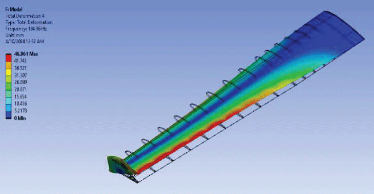
Figure 22: Fluttering Mode 4.
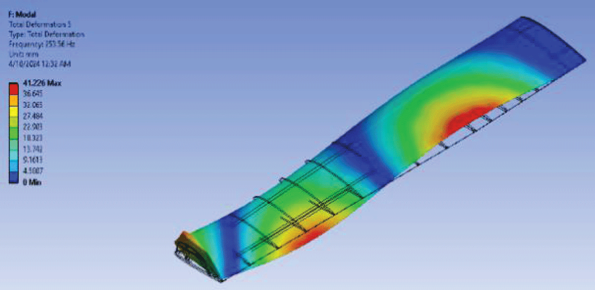
Figure 23: Fluttering Mode 5.
Figure 24: Fluttering Mode 6.
Expanding on this subsection could involve discussing the role of interfacial bonding strength between composite layers and aluminum substrates in determining overall structural performance.
Examining key structural performance metrics such as deformation, stress, and strain further solidifies the superiority of Case 7. The recorded deformation of 51.995, stress of 3.3723, and strain of 0.0016154 demonstrate favourable structural characteristics. These values not only meet safety standards but also indicate a balance between flexibility and strength, crucial for the dynamic demands placed on an aircraft wing during operation.
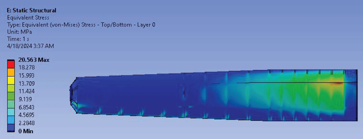
Second optimization problem
The initial optimization (Case 7) reveals critical concerns, particularly high-stress concentrations in the inner wing section and excessive deflections, indicative of potential material integrity issues. Modal frequency and buckling analyses further underscore suboptimal structural behavior, necessitating a reevaluation of the design strategy. Figure 25 shows the stress distribution along the wing inner wing.
Figure 25: Stress Distribution for Optimized Wing 1.
Proposed solution
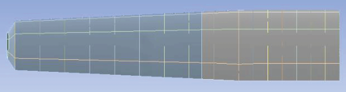
Sectioning and composite orientation adjustment is the optimal solution that could be prescribed in response to the structural challenges identified, a sectional approach is proposed to effectively redistribute loads and enhance overall structural integrity. This entails dividing the wing into sections, each subjected to tailored composite orientations, optimizing stiffness and load distribution across the span. Figure 26 shows the sectioning of the wing into the inner and outer wings. Expanding on the proposed solution to address structural challenges, the implementation of Sectioning and composite orientation adjustment offers a strategic approach.
Figure 26: Wing Sectioning for Optimized Wing Two.
Composite orientation adjustment
Accompanying the sectional approach is a refinement in composite orientation, particularly for the inner wing section where stress concentrations were most pronounced. By transitioning to a [90, 45, 45, 0, 45, 90] composite configuration, the aim is to augment stiffness and resilience, mitigating the adverse effects of stress concentrations and deflections observed in the initial optimization. Figure 27 is the deformation of the wing and Figure 28 is for the stress while strain representation is instituted in Figure 29.
Figure 27: Deformation Optimized Wing 2.
Figure 28: Stress Optimized Wing 2.
Figure 29: Strain Optimized Wing 2.
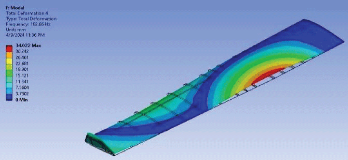
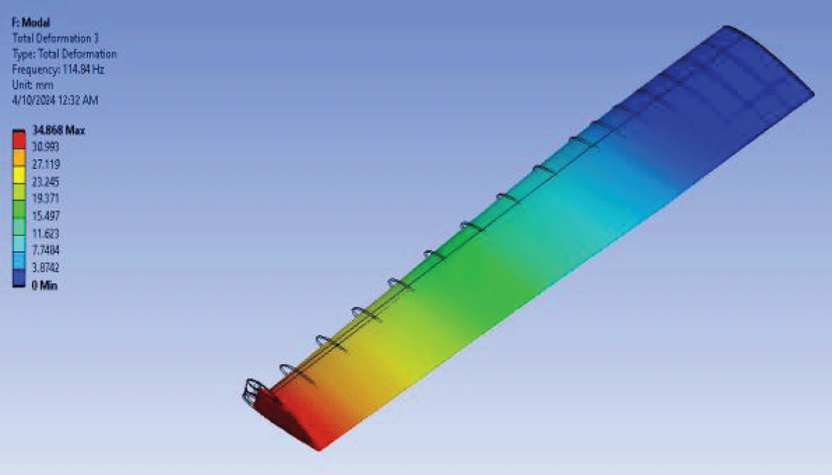
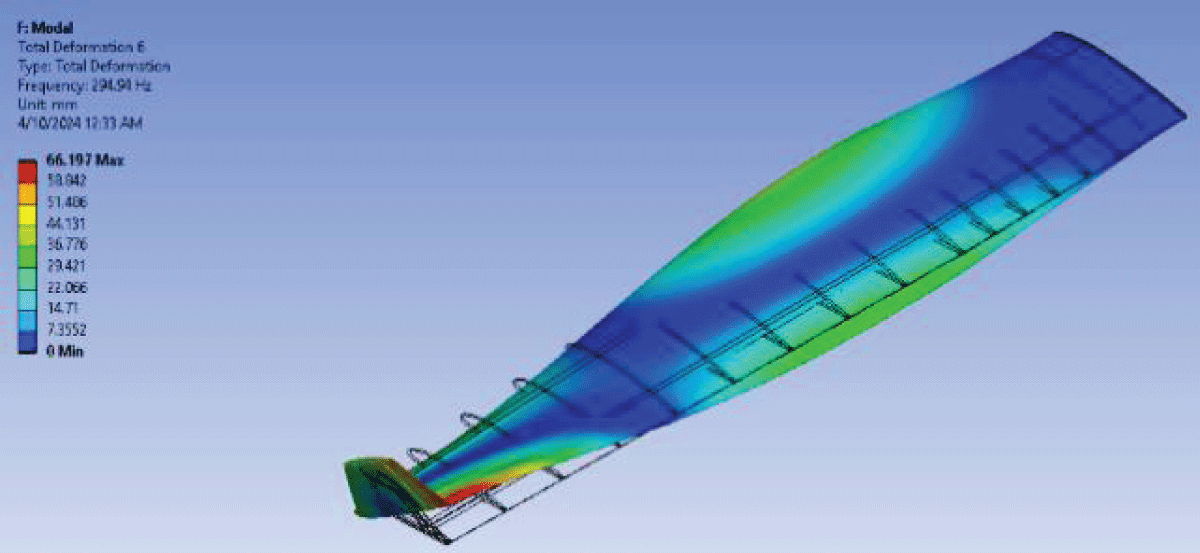
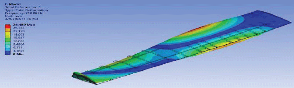
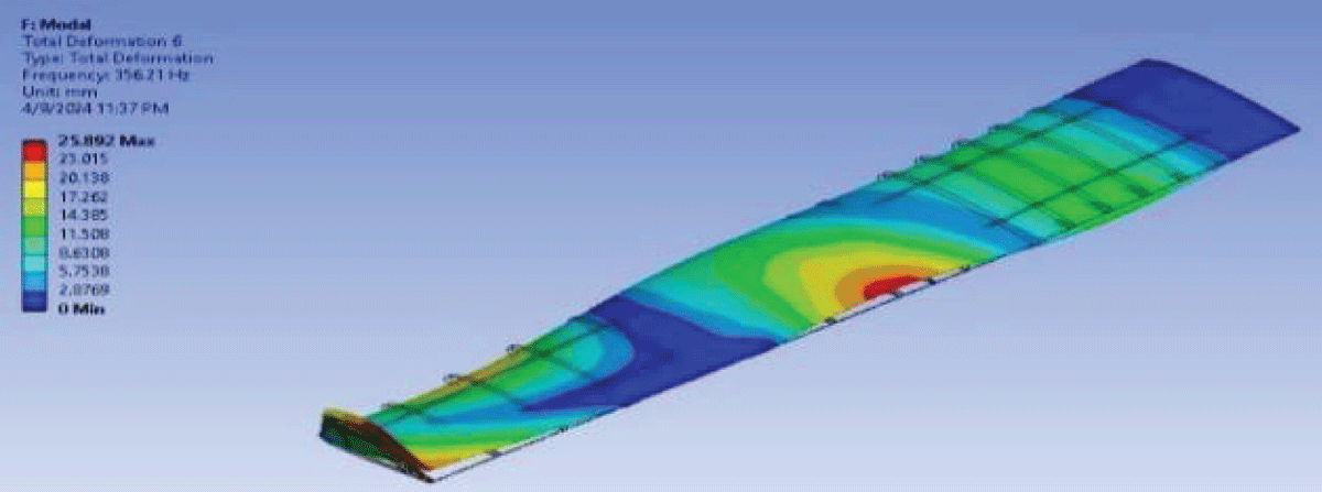
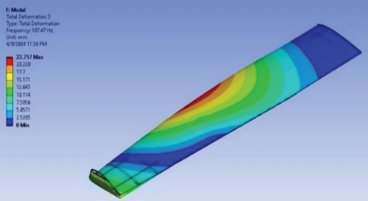
Fluttering frequencies analysis
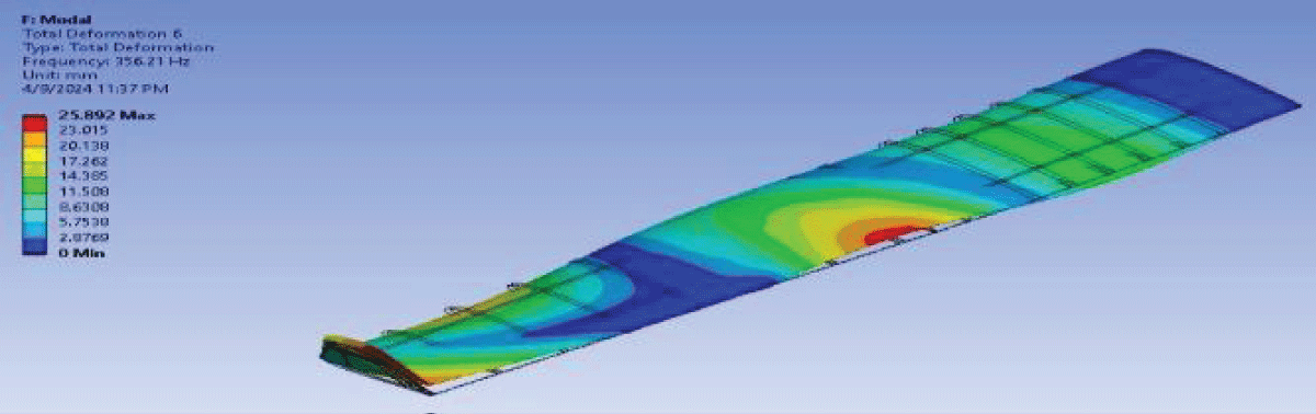
Mode 1 shown in Figure 30 exhibits a frequency of 13.453, indicating the primary oscillation mode of the wing structure. Mode 2 illustrated in Figure 31 with a frequency of 62.693, represents the secondary oscillation mode. Modes 3, 4, and 5 illustrated in Figures 32-35 showcase frequencies of 68.061, 84.944, and 101.39, respectively, signifying higher-order oscillation modes.
Figure 30: Fluttering Mode 1.
Figure 31: Fluttering Mode 2.
Figure 32: Fluttering Mode 3.
Figure 33: Fluttering Mode 4.
Figure 34: Fluttering Mode 5.
Figure 35: Fluttering Mode 6.
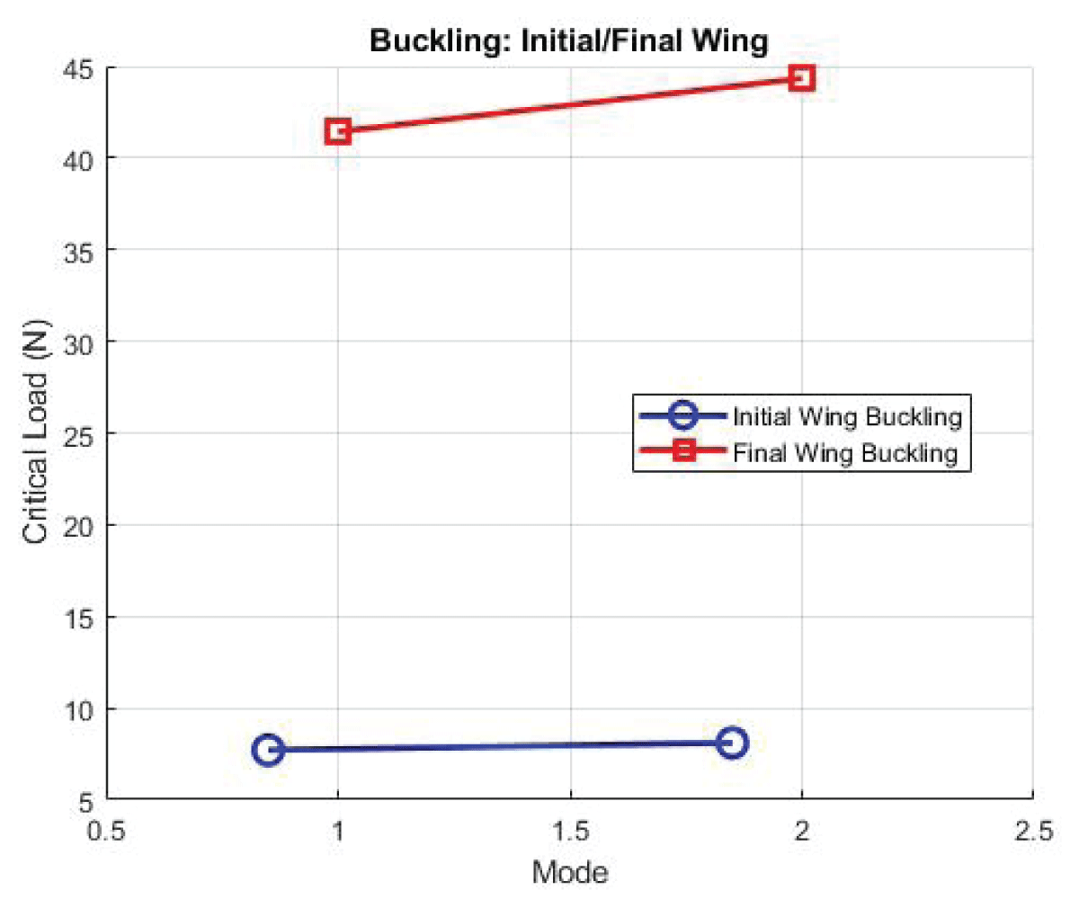
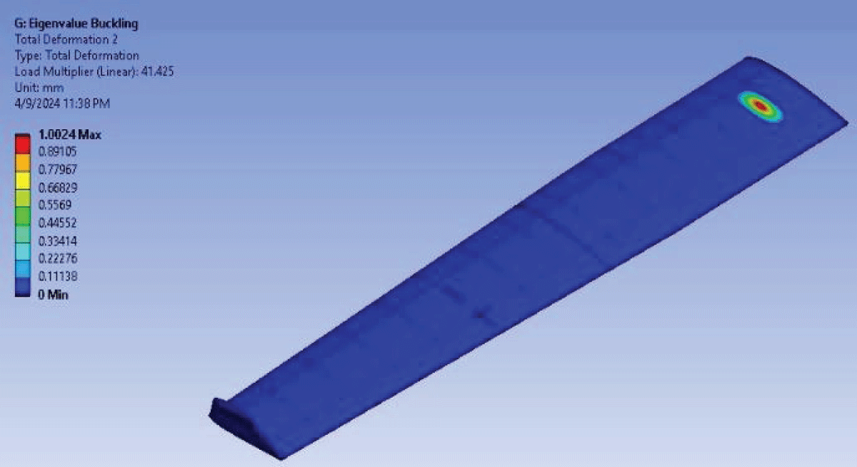
Buckling optimization
Buckling analyses are crucial for assessing the wing’s structural stability under compressive loads. The critical load values represent the threshold at which buckling occurs, highlighting the wing’s ability to withstand compressive stresses without collapsing.
Mode 1’s critical load of 41.425N suggests robust resistance against buckling, indicative of a structurally sound configuration capable of withstanding significant compressive forces as shown in Figure 36.
Figure 36: Buckling Visualization First Optimized Wing.
Comparison optimal and base wing: To underscore the effectiveness of the chosen coupling, a comparative analysis with the base case (no winglet) is essential. The base case, featuring a 6-layer 1.2 mm EGlass/Epoxy skin and low-density balsa wood rib, serves as a benchmark. While the base case exhibits respectable performance, Case 7 outshines it in multiple aspects. The comparison results are showcased in Tables 1-5 between base and optimized wings.
Weight Reduction in Case 1 shows a weight of 3.5299 kg is notably lower than the base case, emphasizing the efficiency of the chosen material coupling in reducing overall weight. A safety factor of 1.875 in Case 1 surpasses the base case, indicating an enhanced margin of safety.
Overall optimization impact
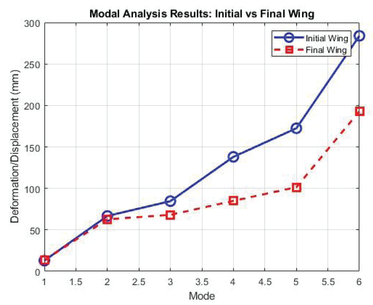
The modal frequencies and critical load values for the second optimization iteration demonstrate substantial improvements in both fluttering resistance and buckling stability compared to the initial model. These enhancements underscore the effectiveness of the optimization strategy, affirming the structural integrity and aerodynamic performance of the refined wing configuration.
Aeroelastic modeling and simulation play a pivotal role in predicting the dynamic response of aircraft wings to aerodynamic loads. By integrating Computational Fluid Dynamics (CFD) simulations with structural analysis techniques, engineers can accurately capture the complex interactions between airflow and wing deformation, informing the design process and optimizing flutter performance illustrated in Table 8.
Table 8: Result Comparison for Base and Optimized Wing.
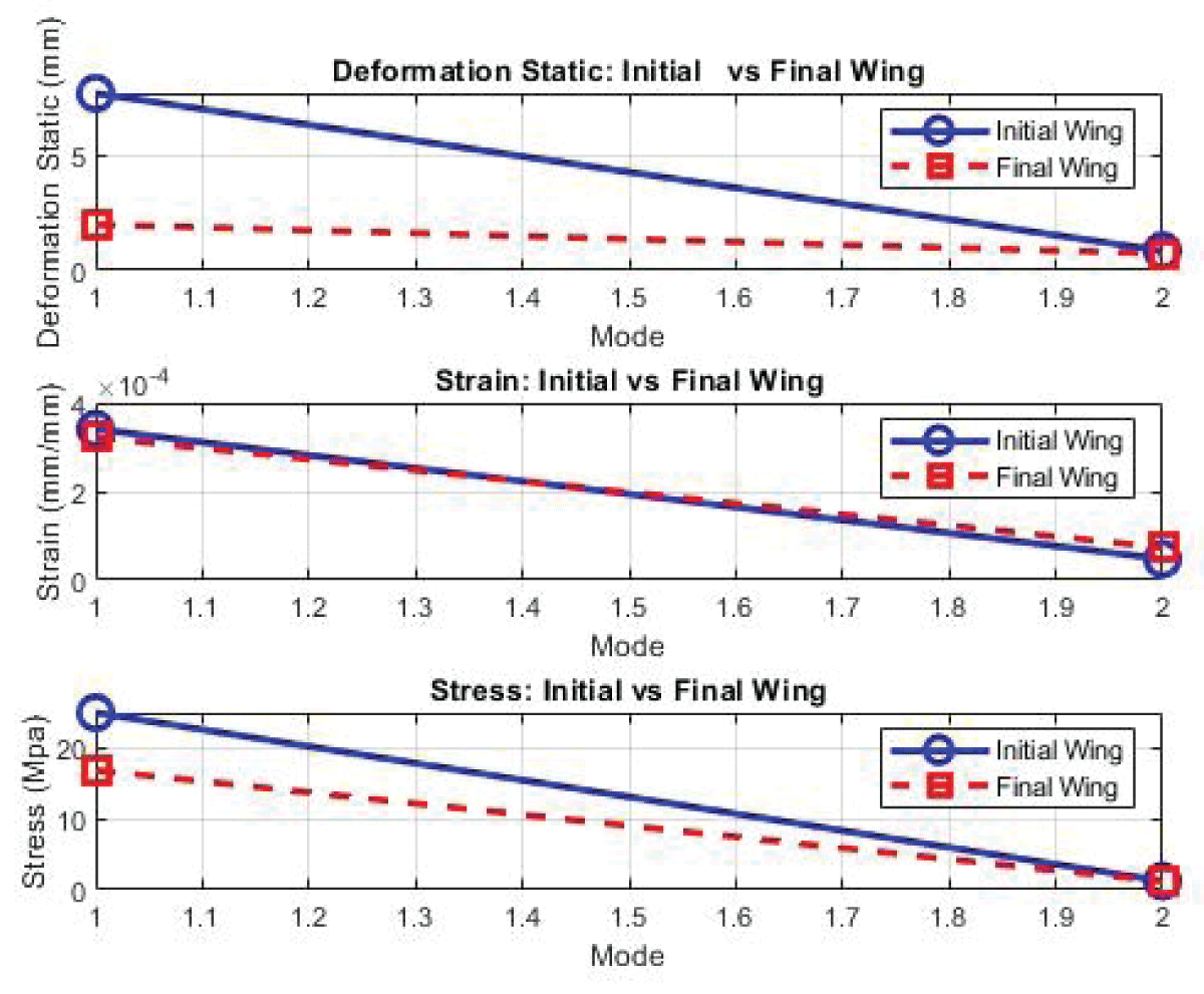
The comparison between the optimized and base wing configurations underscores the effectiveness of design optimization in achieving superior structural performance. With significant reductions in deformation and stress, the optimized configuration demonstrates enhanced rigidity, load-bearing capacity, and safety margins compared to the base case. Case 7 exhibits comparable or improved structural performance metrics, such as deformation, stress, and strain, signifying superior aerodynamic and structural efficiency. The comparison between the base module and the optimized module (Case 7) reveals significant improvements in deformation, stress, and strain. For example, there’s a remarkable reduction of 73.7% in deformation, indicating enhanced structural rigidity and resistance to external loads. Similarly, the stress and strain values have decreased by 4.01% and 2.48%, respectively, in the optimized module, highlighting improved load-bearing capacity and material performance. The static values are listed in Figure 37, and modal values in Figure 38 and Figure 39 for buckling.
Figure 37: Static Analysis Parameter Initial and Final Wing.
Figure 38: Fluttering/Modal Analysis Parameter Initial and Final Wing.
Figure 39: Buckling Analysis Parameter Initial and Final Wing.
The optimized case’s weight of 3.5299 kg is notably lower than the base case, emphasizing the efficiency of the chosen material coupling in reducing overall weight.
The safety factor of 1.875 in Case 7 surpasses the base case, indicating an enhanced margin of safety and resilience. Case 7 exhibits comparable or improved structural performance metrics, such as deformation, stress, and strain, signifying superior aerodynamic and structural efficiency.
The proposed research will look to analyze and optimize the structural configuration of the unmanned aerial vehicle LSU-02 NGLD’s wing. The air-vehicle has a number of research works done on it will allow for easy accessibility to data on the UAV. The secondary analysis discusses the limits of pressure, displacement, and load the wing could carry and also the material property of the wing components. The concluded analysis will help us understand the best approach to utilize when analyzing for further variables.
The selection of Case 7, coupling Epoxy Carbon Fiber with Al 2024 and low-density balsa wood, represents a judicious balance between weight reduction, safety, and structural performance. The methodology employed, integrating coarse grain-fidelity methods for rapid evaluation and fine grain-fidelity simulations for detailed analysis, exemplifies a robust approach to wing design optimization. This comprehensive strategy ensures that the chosen wing configuration not only meets but exceeds the performance expectations, paving the way for the development of highly efficient and reliable UAV wings.
In conclusion, the optimization process for the UAV’s wing structure proved successful, combining both coarse and fine granularity optimization techniques. The addition of winglets not only minimized weight but also enhanced the structural integrity, as evidenced by the reduced deformation and increased factor of safety. The shift from All 7075 to Al 2024 for the wing material indicates a strategic decision to balance weight considerations with structural robustness.
This integrated optimization methodology demonstrates a holistic approach, addressing structural aspects of the UAV. The successful outcomes in weight reduction, deformation minimization, and increased factor of safety underscore the effectiveness of the employed optimization techniques. Overall, these improvements contribute to the UAV’s enhanced performance, making it a more efficient and reliable platform for its intended applications.
Babansoro SA, Zhongmin D, Mehedi H, Islam SM. Integrated Multi-fidelity Structural Optimization for UAV Wings. IgMin Res. May 21, 2024; 2(5): 374-398. IgMin ID: igmin191; DOI:10.61927/igmin191; Available at: igmin.link/p191
Address Correspondence: Sanusi Muhammad Babansoro, Beihang University, School of Astronautical Science and Engineering, Beijing 100083, China, Email: [email protected]
How to cite this article: Babansoro SA, Zhongmin D, Mehedi H, Islam SM. Integrated Multi-fidelity Structural Optimization for UAV Wings. IgMin Res. May 21, 2024; 2(5): 374-398. IgMin ID: igmin191; DOI:10.61927/igmin191; Available at: igmin.link/p191


 スキャンしてリンクを取得